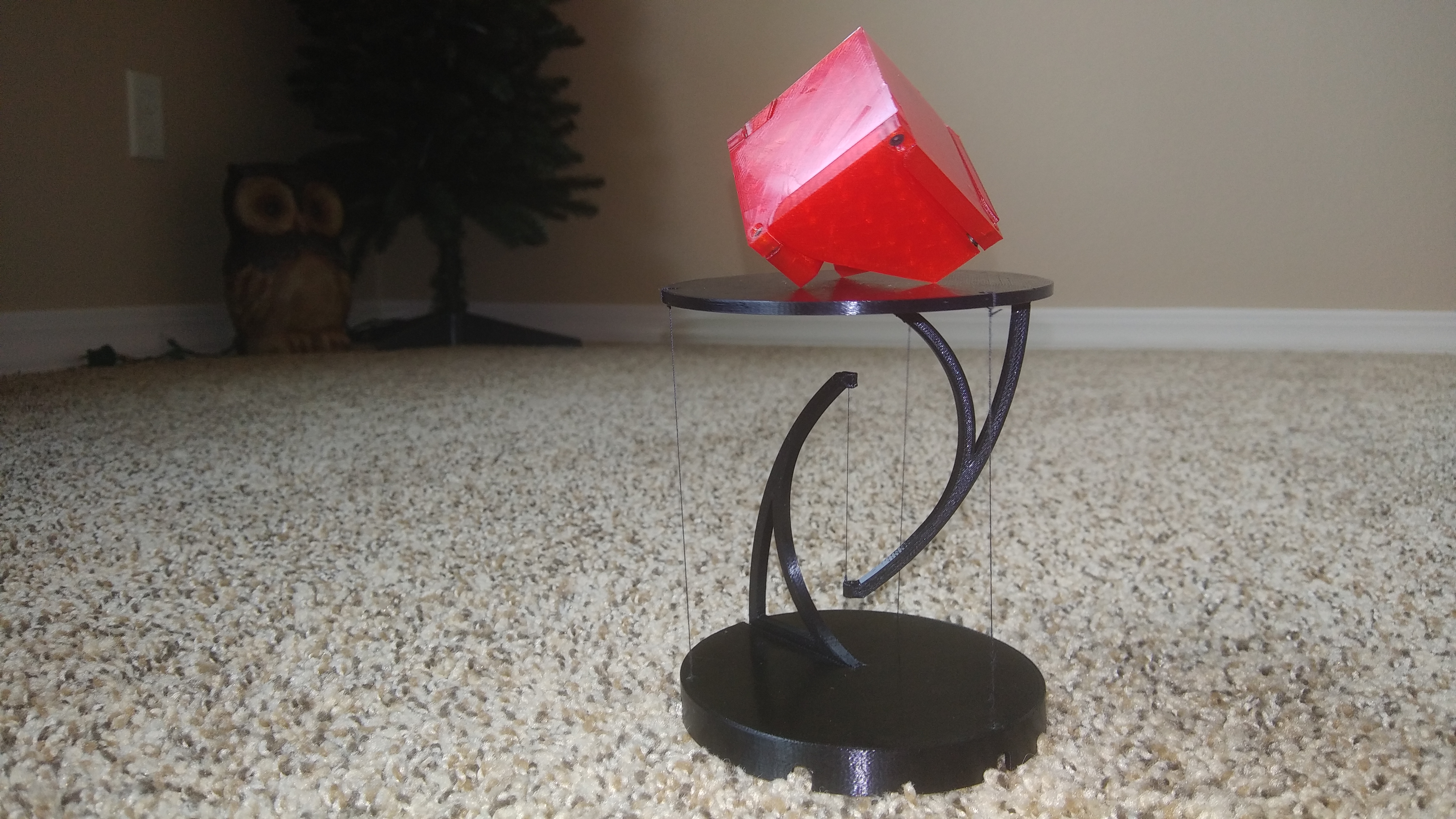
"Floating" tensegrity table with built in tensioning mechanism
prusaprinters
<p>A structure that uses opposing tensioned strings to remain stable. A neat toy/display stand/demonstration piece/conversation starter that is a kind of optical illusion.</p> <p>UPDATE: I have changed the model's version to 2.0. I made some simple geometry modifications. The model no longer uses any m2 screws. All screws are m3 now. The base and top parts no longer require support. Instead, sacrificial bridging is used. 4 holes most now be drilled out with a ~3mm drill bit or an x-acto knife works as well. (The holes do not have to be exact) Below is the updated parts list and instructions. I included the (very very messy) fusion360 files for anyone that wants to alter the models. (If you printed the old V1 files or gcode from the V1 files, you will need 4 m2x8mm screws and 4 m2 nuts to attach the arms to the base and top instead of m3.) The v1 files are still available with an "old_" prefix before the file names. Gcode that i have provided is for PLA with a print temp of 200C, 60C bed, 100% flow, 1mm retraction, 60mm/s print speed, and a 220mmx220mm print bed. Use the gcode at your own risk. After doing some experimenting, fishing line works the best for the strings, but any string will really work.</p> <p>Required hardware:</p> <p>1.) 4 X m3x10mm or m3x5mm hex socket cap screws (For attaching arms to the base and top.)</p> <p>2.) 4 X m3x50mm machine screws (Any length should work, longer is better. I used 50mm length. Longer screws = easier adjustment of tension.)</p> <p>3.) 8 X m3 nuts</p> <p>4.) Roughly 500mm to 1000mm of string/thread/fishing line of your choice (cables that don't stretch much work best.)</p> <p>5.) 4 X m3 washers (Optional)</p> <p>Printed parts:</p> <p>1 X base<br/> 1 X top<br/> 1 X top_arm<br/> 1 X base_arm<br/> 4 X shuttle</p> <p>Assembly:</p> <ol> <li>print</li> <li>drill out the 4 holes on the top and base with a 3mm drill bit</li> <li>attach the top_arm to the top with 2 m3x10 screws and 2 m3 nuts</li> <li>attach the base_arm to the base with 2 m3x10 screws and 2 m3 nuts</li> <li>add the strings to the model (you will assemble the tensioners while adding the string)</li> <li>tension the strings and enjoy!</li> </ol> <p>Stringing instructions:</p> <p>Refer to the diagram above for a visual reference. Attach the base_arm to the base and the top_arm to the top before adding string to the model.</p> <p>It's easiest if you first start with the center string. A string length of 200mm or so is probably a good starting point. First tie one end of the string to the shuttle. Then put the nut in the shuttle and put it in the appropriate guide channel. Thread the shuttle onto the m3 screw so it's just at the tip (do not tighten the screw down yet!). Then put the string through the appropriate hole in the base. The center string runs along the v-channel in the base_arm then through the hole in the base_arm and then through the two holes in the top arm and then it's tied there. Try to leave about 45mm of string between the tips of the top_arm and base_arm. Then repeat a similar set of operations for the other 3 strings. Always start by tying one end of the string to the shuttle, installing the shuttle at the tip of the tensioning screw, and end by tying the other end of the string to the top part. The outside 3 strings should be about 110mm measured from where they exit the base to where they enter the top.</p> <p>Then you can use the screws to adjust the tension of each string. Try to get all the outer strings to be equal length and make sure all 4 strings are tight. You should be able to adjust the height of the top platform somewhat by carefully adjusting all of the string tensions.</p> <h3>Print instructions</h3><p>All parts should import into your slicer in the correct print orientation. I printed all the parts with a 0.4mm nozzle at 60mm/s with 15% infill. I used 4 top and 4 bottom layers. Total print time was somewhere around 3.5 to 4 hours. All of the parts together used around 60 grams of PLA.</p> <p>Arms:<br/> Print the arms with lots of outer walls or lots of infill. You want the arms to be as stiff as possible. I used an extrusion width of 0.5mm and 5 perimeter walls for the arms. layer height shouldn't matter much.</p> <p>Shuttles:<br/> The shuttles should be solid. I just used 5 walls at an extrusion width of 0.5mm. I used a layer height of 0.16mm, but any layer height should work fine.</p> <p>Base and top:<br/> I used an extrusion width of 0.5mm, a layer height of 0.24mm and 3 perimeters for these parts. V2 parts use sacrificial bridges. No support is required for these parts. After printing, use a ~3mm or similarly sized drill bit to open 2 holes in the base and 2 holes in the top. Refer to above pictures.</p>
With this file you will be able to print "Floating" tensegrity table with built in tensioning mechanism with your 3D printer. Click on the button and save the file on your computer to work, edit or customize your design. You can also find more 3D designs for printers on "Floating" tensegrity table with built in tensioning mechanism.