Flux Engine (Stand-alone)
prusaprinters
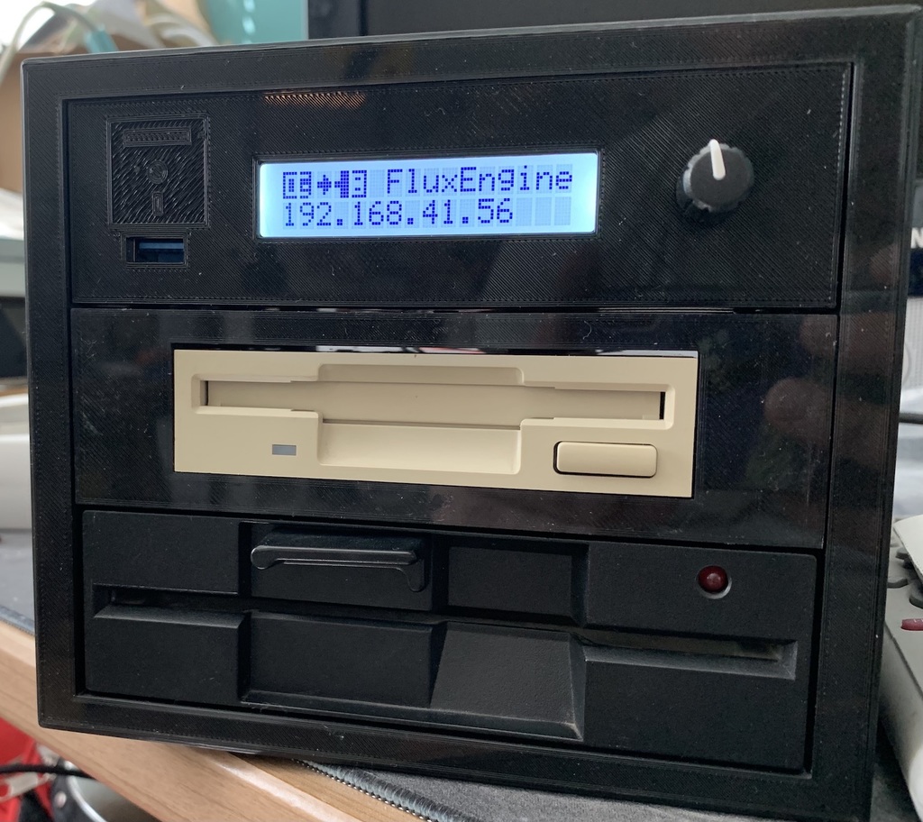
<h3>— import to PrusaPrints messed up the formatting, please see the <a href="https://www.thingiverse.com/thing:4876846">thingiverse page</a> for a better reading experience —</h3><p> </p><h3>A stand-alone FluxEngine based on the magnificent work done by David Given</h3><p>(<a href="http://cowlark.com/fluxengine/">http://cowlark.com/fluxengine/</a>)</p><h3>~This project is in active development.~ Project development currently on hold for re-evaluation.</h3><h3>Current status is:</h3><ul><li>hardware 100%,</li><li>software 10%,</li></ul><p>3d-printed parts design: 99% I plan to create a video of the complete assembly.<br>I am no longer planning to create an assembly video for a number of reasons.</p><p>The build I am currently using is a development build with port extenders (USB, HDMI, LAN) so the video would not be representative.</p><ul><li>The build is not difficult to figure out without visuals but it is a tedious job which I don't like to repeat over and over to get a good video.</li></ul><p>Response to this design has been disappointing and I probably will change a lot in the coming months. ### Incompatibilities:</p><p>The current back-panel uses a USB-C port with a power delivery PCB. In recent testing I found the board to be underperforming (that is an understatement). None of the 10 boards I have managed to produce a stable 20 volts supply under even minor load.<br>I drilled out the hold and mounted a simple socket for a laptop power supply.<br>The back-panel will be redesigned for this.</p><h3>Print Settings</h3><p><strong>Printer Brand:</strong></p><p>Creality</p><p><strong>Printer:</strong></p><p>Ender 3</p><p><strong>Rafts:</strong></p><p>No</p><p><strong>Supports:</strong></p><p>Yes</p><p><strong>Resolution:</strong></p><p>.2</p><p><strong>Infill:</strong></p><p>50%</p><p><strong>Filament:</strong> REAL PLA Black<br><strong>Notes:</strong></p><p>some parts require supports, some don't, some are high infill, some are low infill. See below for details.</p><h3>Index</h3><ol><li>3D Parts</li><li>Electronics required</li><li>Hardware required</li><li>Wiring</li><li>Software</li><li>Printing/assembling guide</li></ol><h3>1. 3D Parts</h3><p>Main body print once, as a tube upward; open end on the build plate and use supports on build plate. you should only have support in the four corners.</p><p>This part takes about 170 meters of 1.75 filament, about 500 grams, and takes about 3 days to print (for me on my Ender 3, at least), so make sure you only need to print this once!</p><p>about 30% infill should be enough</p><p>The main body is designed to be reversible; it does not matter which end you use as front or rear.</p><p>Front bezel print face down, should not require supports, about 40% infill should do the trick</p><p>Back panel print back-face down, requires supports for the bolt holes. You can easily remove them by screwing in a bolt from the inside. About 40% infill should be ok. The grill for the fan requires a .2 layer-height to print. You can get away with .1, but I advice against it. This is because of the way the grill is designed and can be seen in many other projects I created.</p><p>feet (x4) print with TPE/TPU for optimal effect, or skip and use stick-on rubber feet.</p><p>drive rails (x6) print with 50% infill, probably need to lower skirt-distance or skip a skirt altogether.<br>Due to inaccuracies the 14mm rail was too tight fit to slide in, so I added a 13.5 and 13mm version. The trick is to have one installed that does not rattle, but also slides in without problems.</p><p>3,5 to 5,25 inch adapter. print face down (for glossy front) or bottom down (for less support) with support everywhere. This is tough to clean up, but I haven't found way to print it without supports. Don't bother cleaning out the supports from the bottom and secure the floppydrive from the sides. This part is not designed by myself, but I did change it to meet accurate dimensional requirements.</p><p>electronics bay print bottom on the plate with supports so the cavities for the nuts are nice and clean.<br>Supports on build plate should be enough</p><p>front for electronics bay print face down, no supports needed.</p><p>raspi riser (x4) print straight up, or use other methods to mount the Raspberry Pi about 1cm above the plate.</p><p>USB Extension cable bracket The current design had "snap in bolts" in mind, but that doesn't work as well as I hoped. It works with 4 m2x20 bolts, but it is far from perfect. Remix where needed!</p><h3>2. Electronics</h3><p>Cypress Cy8ckit-059 microcontroller (and access to a Windows 10 computer to program it)<br>instructions on how to program the controller can be found on Davids website cowlark.com.</p><ul><li>Floppy drives. This project is for 2 drives and it makes sense to use 1 3,5" and 1 5,25" drive. Especially 5,25" drives are getting rare! For C64 floppies you need a 360k drive. If you want more supported formats, try to find a 1.2M drive.</li><li>power supply. A laptop power supply (19v 60W). Any power supply over 12volts will do with at least 40 watts. This project as it is described here expects a 14 volt or higher supply.<br>If you plan to use a 12volt supply you can drop the DC/DC converter for 12 volts.</li><li>Raspberry Pi 2B+ or better (I used a 4B+ as I had it in stock)</li><li>16x2 LCD Display</li><li>Rotary knob (either with a break-out board, or a ring-nut)<br>I still haven't found a way to reliably use the rotary knob so I might drop it in favour of 4 microswitches instead</li><li>120x12mm fan (12volts)</li></ul><p>3x DC/DC converters; I used these:<br>one is set for 12volts, one for 5volts. These are used to power the drives and the fan.<br>the third one is set for 5.1 volts and used solely to power the RaspberryPi 4B+ as it requires 15 watts peak (3 amps). <strong>Electronics almost done. Cy8ckit board still missing in this picture.</strong></p><h3>3. Hardware</h3><p>4x M3x20 with nut for mounting the fan. If you use a bigger fan (and remix the back-panel to make room for it), you need longer bolts</p><ul><li>4x M3x12 for securing the back-panel</li><li>4x M3x5 bolt or grub-screw for securing the front-bezel</li><li>2x M3x5 grub screw to secure electronics front-plate to electronics plate<br>Initially I wanted to use regular bolts, but found it difficult to build the project that way. The front fonts quite snug in the plate and the screws are just precaution, you can skip them if you find the front is mounted securely enough.</li><li>16x M3x8 bolts to mount floppy drive(s) and adapter-/electronicsplate(s)</li><li>4x M3x20 with nut to secure the Raspberry Pi (as I always do; the pi has M2.5 holes but with MUCH CARE you can ease an M3 bolt in there using the half-turn-in, quarter-turn-out back-and-forth method)</li><li>12x M3x8 with nut to secure the DC/DC buck converters</li><li>1x M3 bolt or screw with a non-conductive washer to secure the Cy8ckit development board</li><li>4x M2x20 bolt to mount the USB-port to the front</li><li>2x M2x5 bolt to mount the rotary knob</li></ul><p>4x M3x5 bolt to secure the display module</p><h3>4. Wiring</h3><p>floppy cable. The cable is 1.27mm pitch, the connector 2,54mm. 34 wires/pins. the 5.25" drives use an edge-connector, 3.5" and the controller use an IDC connector</p><ul><li>power cable for the pi (either micro USB or usb-c),</li><li>micro-usb 90-degrees cable for the Cy8ckit board (or remix the mount to make room for a straight plug)</li><li>USB extension cable (see below for the one I used)</li><li>17x1 or 17x2 header-pins to solder on the Cy8ckit board.</li><li>Molex plugs with cable for both 3.5" and 5.25" connections. I rescued a cable from a scrapped computer power-supply, but these still are widely available.</li><li>cable to power the 3 DC/DC converters.</li><li>5-wire cable with 5x1 Dupont on one side and 5 1x1 Dupont on the other to attach the rotary knob to the pi. This uses pins 14, 16, 18, 22 and 17 (GPIO 23, 24 and 25, ground and 3.3 volts)<br>Information to follow: which GPIO pins are CLK, DT and SW</li><li>4 wire cable with 4x1 Dupont one side and 4 1x1 Dupont on the other to attach the I2C interface on the display to the pi on pins 3, 4, 5 and 6 (GPIO 2 and 3, ground and 5 volts) <strong>KY-040 Rotary module</strong></li></ul><p><strong>display to I2C module</strong></p><p><strong>1602 LCD module</strong></p><h3>5. Software</h3><p>Currently, In my head, I designed how I want the menu/UI to be on the display, but I need to learn how to program the display and in Python, so this will be the biggest challenge for me :)</p><p>As you can see in the photo, I got the display to work, with a few icons created (later realising there is only room for 8 custom chars)<br>The display will show "booting..." on start-up and show the screen in the photo when done.<br>The rotary knob currently should draw a vertical line in the bottom row (where the IP is now), each pixel equals one disk track (16 chars, 5 wide -> 80 :) ). Although this is mainly to debug the rotary knob, I really would like this to be the progress indicator when reading/writing disks.</p><p>If you have experience with Python on the RasPi, and with 16x2 LCD displays/rotary knobs on the GPIO of the pi, and want to help me, feel free to contact me.</p><p>For this reason I am planning to add an HDMI and 2 USB sockets to the back panel to connect the unit to a monitor and keyboard/mouse so development will be easier.</p><h3>6. Printing/Assembling guide</h3><h3>hardware (printed parts and drives)</h3><p>My advise is to start with printing the main body. This print will take a long time, and is critical to the unit.</p><p>Once printed, print the "Rail height test pieces". You will want the test piece to freely slide in the rail-guides.<br>Now, print 6x the rail in the height you need.</p><p>Unless you are using 2 5,25" floppy drives, print 1 or 2 3,5" drive adapter, depending on your need.</p><p>Print the front bezel and the electronics bay.</p><p>The front bezel is held in place with 4 M3x5 bolts. When mounted, the screws will not be visible once the drives are inserted.</p><p>Print the 4 feet, if you want, and mount them in the bottom of the housing.</p><p>The back has a 6mm hole for Power supply, and it is very close to the fan. I am contemplating a different design. For now you might want to remix to your needs.<br>The alternative back has much more space internally (for the fan) and has cutouts for power switch, USB PowerDelivery board and soon a version with additional USB and HDMI ports will be uploaded.<br>Which ever you want, downloaded, remix it where needed and print it :)</p><p>Depending on your wishes, you might want to remix the front for the electronics bay. When satisfied, print it and slide it in from the top. It should be snug, but if it is too loose, secure it with 2 grubscrews. If you don't have grubscrews, use regular ones but be sure to screw from the INSIDE, otherwise you won't be able to slide the unit all the way in the housing.</p><p>Print the rail-alignment tool and the washer-gauge.</p><p>Mount two rails to the bottom drive and insert the drive into the housing.<br>Place the unit on its side (gravity is a beautiful thing) and insert the washer gauge in the gap between housing and rail. Don't force it. Read the last number that slides in.<br>The number indicates the thickness of washer you need on both sides. (if the gap is 1.2mm, you will read 06 for 0.6mm on both sides, just to be clear ;) )</p><p>In your slicing program, scale the washer (Z-axis only) to the desired thickness and print 4. I would suggest TPU or TPE as it will function as a vibration dampener. (not much but still)<br>Unmount the rails and re-mount with washers.<br>This time use the alignment tool to make sure the rail is in the exact position for the drive to be flush with the front bezel.</p><p>Repeat this process with the top drive (middle slot) and the electronics bay.</p><p>Slide everything in the housing. They now should be perfectly aligned in center horizontally and flush with the front-bezel.</p><h3>If you find the gap on the sides of the drives too large for comfort, remix the front-bezel and replace it.</h3><p>You can now archive the alignment tool, the washer-gauge and the rail-height test pieces.</p><h3>electric and electronic connections.</h3><p>The rotary knob and display need to be connected to the GPIO connector as listed above.</p><p>If you use the same USB extension cable as I do, print the mount for it and mount the usb socket. If you have a different one, you probably need to remix the front and design a mount that holds the port in place firmly, but does not crush it.</p><p>Mount the fan in (or on) the back-panel. In case of "on the outside" the wire will need to be routed to the inside. Use your imagination :)</p><p>When using the first version of the back panel, the power cables and flatcable will probably interfere with the fan. It did for me, so probably will want to mount the fan on the outside.<br>The second version should have ample space for the cables and fan to coexist peacefully.</p><p>From my Ender-5 lid project (<a href="https://www.thingiverse.com/thing:4774618">https://www.thingiverse.com/thing:4774618</a>), download and print a fan guard, if you want one.</p><p>Make sure the voltage are correct. Use the schema below and be absolutely sure that the 12v and 5v wires are not mixed up; you will irreversibly damage your floppy drives if you do this wrong.</p><p>Regarding a power switch;</p><p>Wire the input power (+) from the socket you use to the switch, and from the switch to the 3 DC/DC converters. If you have a switch that toggles two connections at once (4 terminals), the ground wire can be toggled as well, but I think it might be better to keep the ground connected at all times.<br>Make sure the toggle switch is rated for at least 5 amps (it should only require 3, but better sure than sorry)</p><h3>Floppy IDC cable</h3><p>Most floppy drives are hard-wired for "drive 1" or "B". To get a drive to be "drive 0" or "A", a twist in the cable is needed. Most standard 2-drive cables already have this twist.<br>If you have configurable floppy drives (a lot of older, "vintage" drives have jumpers or switches) you can create a single "all straight wired" cable with the appropriate connectors. you need 1 IDC 34pin connector on the controller, same for any 3,5" floppy drive.<br>Most 5,25" floppy drives have an edge connector, some have an IDC connector.</p><p>Either use a new-old-stock, or recycled cable with the connectors you need, or create your own with the appropriate tool, or a good vice. Be aware of pin 1 for all devices and plug in the cable.</p><p><strong>A classic floppy drive cable that services 2 floppy drives of any type, configured as "Drive 1" or "B".</strong></p><p>Apart from a few bolts you should now be done with assembly.</p><h3>Software</h3><p>Currently, there is no working software package, but when I do, it should go something like this.</p><p>Install the RaspberryPi using any guide on the web, you will probably want WiFi configured and SSH enabled. In the finalised project, you will not need to access the Pi directly unless there is debugging or maintenance to do.</p><p>Then download the software from my GitHub (link to follow) and follow the installation guide that is included there. (It will probably be something like; run install.sh and reboot)</p><p>Once done, you can operate the unit using the rotary knob and display.</p><p><strong>HDMI Breakout for RasPi's with a large connector</strong></p><p><strong>HDMI Breakout for RasPi's with a small connector, might need to trim the plug, will see when I receive it.</strong></p><p><strong>USB backpanel for keyboard/mouse.</strong></p><p><strong>USB cable, 3d rendering by seller, should be pointing down and length 15cm should be enough</strong></p><p><strong>links</strong></p><h3>Disclaimer; I have linked the items I ordered below. I am not affiliated with any of the sellers and I am not ordering you to buy here. I just want to show which ones I bought and for which this is designed.</h3><h3>If you find a different product or a different seller; go for it, remix the parts where needed</h3><p><a href="https://www.aliexpress.com/item/Ribbon-Flat-USB-3-0-Cable-Super-Speed-USB-Extension-Cable-Male-to-Female-0-5m/4000325514771.html">https://www.aliexpress.com/item/Ribbon-Flat-USB-3-0-Cable-Super-Speed-USB-Extension-Cable-Male-to-Female-0-5m/4000325514771.html</a><br><a href="https://www.aliexpress.com/item/ILEPO-GAN-65W-USB-C-Charger-Quick-Charge-QC4-0-PD3-0-USB-C-With-100W/1005001587622997.html">https://www.aliexpress.com/item/ILEPO-GAN-65W-USB-C-Charger-Quick-Charge-QC4-0-PD3-0-USB-C-With-100W/1005001587622997.html</a><br><a href="https://www.aliexpress.com/item/Type-C-USB-C-PD2-0-PD3-0-to-DC-Spoof-Scam-Fast-Charge-Trigger-Polling/4000525077957.html">https://www.aliexpress.com/item/Type-C-USB-C-PD2-0-PD3-0-to-DC-Spoof-Scam-Fast-Charge-Trigger-Polling/4000525077957.html</a><br><a href="https://www.aliexpress.com/item/50cm-Gold-Plated-High-Speed-Micro-HD-MI-Male-to-HD-MI-Female-Extension-Cable-with/4001128778567.html">https://www.aliexpress.com/item/50cm-Gold-Plated-High-Speed-Micro-HD-MI-Male-to-HD-MI-Female-Extension-Cable-with/4001128778567.html</a><br><a href="https://www.aliexpress.com/item/HDMI-compatible-A-1-4-19pin-Male-To-HDMI-compatible-A-Type-Female-Extension-Cable-With/32829168114.html">https://www.aliexpress.com/item/HDMI-compatible-A-1-4-19pin-Male-To-HDMI-compatible-A-Type-Female-Extension-Cable-With/32829168114.html</a><br><a href="https://www.aliexpress.com/item/Dual-Port-USB-2-0-A-Male-to-Female-M-F-Extension-Screw-Lock-Panel-Mount/4000581242162.html">https://www.aliexpress.com/item/Dual-Port-USB-2-0-A-Male-to-Female-M-F-Extension-Screw-Lock-Panel-Mount/4000581242162.html</a><br><a href="https://www.aliexpress.com/item/15CM-RJ45-Short-Cable-Male-to-Female-Screw-Panel-Mount-Ethernet-LAN-Network-Extension-Cable-rj45/10000348649620.html">https://www.aliexpress.com/item/15CM-RJ45-Short-Cable-Male-to-Female-Screw-Panel-Mount-Ethernet-LAN-Network-Extension-Cable-rj45/10000348649620.html</a><br><a href="https://www.aliexpress.com/item/5pcs-Lot-360-Degrees-KY-040-Rotary-Encoder-Module-Brick-Sensor-Switch-with-15x17-mm-Potentiometer/1005002438780645.html">https://www.aliexpress.com/item/5pcs-Lot-360-Degrees-KY-040-Rotary-Encoder-Module-Brick-Sensor-Switch-with-15x17-mm-Potentiometer/1005002438780645.html</a><br><a href="https://www.aliexpress.com/item/KCD4-201-30x22-30A-250VAC-Heavy-Duty-KCD4-Rocker-Switch-20A-250VAC-DPST-ON-OFF-latching/33041128258.html">https://www.aliexpress.com/item/KCD4-201-30x22-30A-250VAC-Heavy-Duty-KCD4-Rocker-Switch-20A-250VAC-DPST-ON-OFF-latching/33041128258.html</a>?<br><a href="https://www.aliexpress.com/item/LCD1602-1602-Module-Blue-Green-Screen-IIC-I2C-16x2-Character-LCD-Display-Module-1602-5V-Green/1005002035425652.html">https://www.aliexpress.com/item/LCD1602-1602-Module-Blue-Green-Screen-IIC-I2C-16x2-Character-LCD-Display-Module-1602-5V-Green/1005002035425652.html</a></p><p>Category: Computer</p>
With this file you will be able to print Flux Engine (Stand-alone) with your 3D printer. Click on the button and save the file on your computer to work, edit or customize your design. You can also find more 3D designs for printers on Flux Engine (Stand-alone).