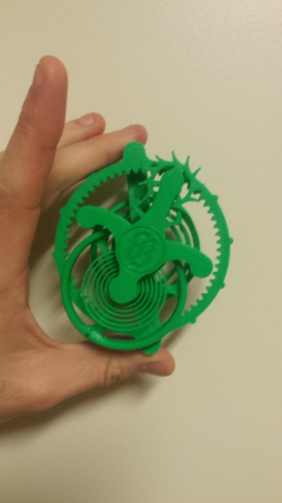
Flying Tourbillon Model 1.5
thingiverse
I finally got around to improving my first tourbillon model. For more information on the design and a brief lesson in amateur horology, see the original at: https://www.thingiverse.com/thing:1991251. See this one in action at: https://www.youtube.com/watch?v=QvW-A2oI-O0 Changes include the following: - Guard pin to prevent mis-alignment of the fork - Spring powered (about 40s run time (or you can pretend that it's a fidget spinner and keep winding it)). - Replacing 3mm bearings with one 608 bearing so that now one must only cut 3 x 2mm shafts (I use a small piece of PLA filament to pin the balance spring in place). UPDATE 25JAN18: I added some exploded views to assist with assembly. Also, my record for runtime is now 58 seconds. UPDATE 30JAN18: I uploaded new versions of five parts with narrowed holes to support PLA filament shafts so that there isn't too much slop. All have "-PLA shaft" in their title. I have yet to test them (soon, I hope), but they use hole diameters that have worked previously with PLA shafts in my designs. If one wants to avoid metal parts entirely, (smuggling plastic tourbillons through the TSA?) here is a list of 608 bearing replacements located on Thingiverse. I have not tested these designs personally and I'm sure that there are many other suitable variants. Using 4.5mm BBs: https://www.thingiverse.com/thing:2598427 Fully printed: https://www.thingiverse.com/thing:2375580 More of a bushing but should still work (design includes STLs for different amounts of slop): https://www.thingiverse.com/thing:2482146 UPDATE 14FEB18: I got a PLA shaft version working. It does not run as smoothly as the metal shaft version due to increased plastic-on-plastic friction. Here are some observations from tuning it: -I find PLA shafts work best with the shaft locked into the rotating part with the ends spinning in the socket in the frame (individual results may vary). Be sure to sand almost hemispherical ends into the shafts. -Tolerances also needed the be tighter. If the escape wheel and the anchor shift closer together, they will lock up. - I printed all parts for my PLA shaft version on my $160 monoprice mini delta at warp speed with very cheap filament. I ended up having to sand the escape wheel teeth to make them thinner due to resultant slop and overextrusion at the turns (note: be careful not to make the teeth shorter when sanding). It also took two attempts to get a useable anchor part. - I corrected the PLA shaft anchor part so that the guard pin is now in the same position as the metal shaft version (good catch user Chukklehed). Flipping the roller upside down during assembly would have solved the issue with the previous file -Nozzle size on my printers is .4mm and much of the geometry in the model results from this value. For instance, depending on how your slicer operates, it might be impossible to print the .8mm thick escape wheel teeth with a larger nozzle. -This design is based on stiff PLA. More flexible materials (eg. Nylon or PETG) might deform and thereby decrease the performance of the design. Springs made from more flexible filaments also have less power so expect less from the mainspring and a longer period from the balance (fewer but slower ticks per winding). UPDATE 5MAR18: I've uploaded some new files to address concerns identified by user NikoKun in the comments section. My response as follows: "I noticed similar issues recently when printing this design on my new Prusa i3 mk3 kit coupled with Slic3r. Previously, using my Reach 3D printer with Cura, holes came out undersized, so I incorporated offsets in all of my designs to ensure parts printed with the correct dimensions. I found, however, that printing the "PLA shaft" files on the Prusa yielded the correct tolerances for 2mm metal shafts to prevent excessive wobble and slop. If you know what works best for your printer, it should be fairly easy to mod the parts within Openscad (import the .stl, then code in a difference of cylinders). "That still leaves the balance assembly, however...Ideally, it should spin freely, and there should not be any wobble on the balance staff assembly as that could cause the balance wheel to tilt and rub against the fork or the frame." To address issues in the balance staff, I uploaded new versions of the roller and the balance wheel with tighter tolerances. They say "tight" in the file name. To prevent the tourbillon cage from wobbling and causing the escape wheel pinion to skip teeth on the fixed annular gear, I uploaded "frameb-3-tight.stl" to provide a better fit without blue tape in the 608 bearing. As for adjusting the balance spring: "...[instead] I usually make adjustments to the balance wheel through grub screws or by changing the infill density. I've printed this design with PLA from Hatchbox, Prusa, and AO Robotics and the springs all perform about the same." I added a stiff version of the balance spring that should provide 1.5x stiffness for more supple plastics. Please note, however, that I have not tested this spring. Thanks to all who have posted makes of this design. I've enjoyed seeing the different interpretations. 04MAR18: I posted an instructable. I hope it clarifies some issues. https://www.instructables.com/id/3D-Printed-Tourbillon/
With this file you will be able to print Flying Tourbillon Model 1.5 with your 3D printer. Click on the button and save the file on your computer to work, edit or customize your design. You can also find more 3D designs for printers on Flying Tourbillon Model 1.5.