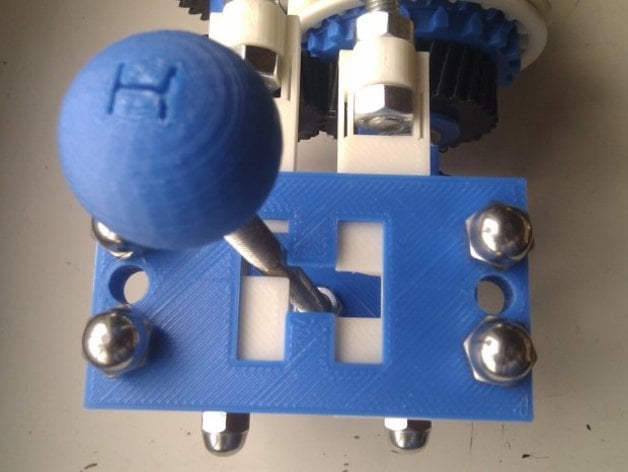
Four speed gearbox with H shifter
thingiverse
A four-speed gearbox has gears with specific teeth and ratios. First gear has 40 teeth and a 2.22 ratio. Second gear has 38 teeth and a 1.72 ratio. Third gear has 36 teeth and a 1.38 ratio. Fourth gear has 32 teeth and a 1.00 ratio. The threaded rod is 8mm in diameter. The gears, hubs, and other components are held on the threaded rod with jam nuts. In the future, bearings will be used instead of some stands. To see how it works, visit this YouTube video: http://youtu.be/zyc-CCEKLo8 To print the gear cassette assembly, you need: * assem_gear1.stl (x8) - four gears have lugs to fit baulk rings * assem_baulk_holed.stl (x4) * assem_hub.stl (x4) * assem_spacer.stl (x2) * assem_stator.stl (x2) * assem_selring_grooved.stl (x2) * assem_fork_holed (x2) To print the H shifter, you need: * assem_hlower.stl (x1) * assem_hplate.stl (x1) * assem_pivotbar_grooved.stl (x1) * assem_slider_pair.stl (x1) * assem_gearknob.stl (x1) Hardware needed: * About a meter or more of threaded rod * Around 40-50 nuts * About 15 washers Operation: Each shaft has one selector ring set. The selector ring sits on top of the stator when in neutral position. The gears spin freely on their hubs. When you shift either way, it locks a baulk ring to the stator, engaging the corresponding gear. Assembly (stators and baulk rings): On an 8mm threaded rod shaft, add a stator, then add a baulk ring on each side with triangle teeth pointing towards the stator. Put a selector ring over the stator. Assembly (hubs and lugged gears): Place a hub flanged end up and slip a gear (gear1a) over it with lugs facing upwards. Attach both to a shaft and mate the lugs into a baulk ring on each side. Assembly (gears 3 and 4): Repeat the assembly process, but this time for gears 3 and 4. Assembly (shaft locking): For each shaft add washers and jam nuts at each end, then tighten. The stators, spacers with gears will be locked while the 4 gear hubs spin freely. Assembly (stands): Insert the shafts into stands using more threaded rod across them to keep the shafts apart by 51mm. Assembly (H Shifter and forks): Check the photos for now. Gear cassette known constants: * The shaft centers are 51mm apart. * The travel from neutral to select any gear is 6mm. Known issues with the gearbox: Too much threaded rod but it's adjustable. The setup feels a bit clunky, and the forks could be smaller for more precision. The H box sits on rotating shafts; a standalone stand would really make sense.
With this file you will be able to print Four speed gearbox with H shifter with your 3D printer. Click on the button and save the file on your computer to work, edit or customize your design. You can also find more 3D designs for printers on Four speed gearbox with H shifter.