FoX Z(X) 50mm Axis - Anycubic I3 Mega or any (custom 3d printer) - X-Gantry system
thingiverse
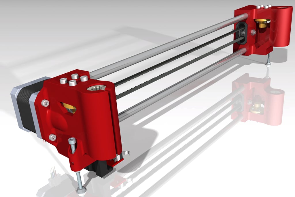
Custom designers can upgrade the Anycubic I3M Z(X) axis to solve its most severe design flaw: a weak, wobbly, flimsy original Z(X) axis. This modification adds a clear visual upgrade to 3D prints, making their quality comparable to that of legendary Prusa printers. A decent extruder is required too - for example, the BMG clone used on a Bowden machine looks capable of handling tasks. The new axis is fully compatible with the original Anycubic 50mm X-gantry system and can be used in any Anycubic I3M configuration, including original or customized X carriages, cable chains, extruders fixed to the Z axis (original design), on top of the frame, or direct drive. The RHS carriage features a built-in belt tensioning system, solving another missing feature of the original Anycubic design. Costs for this modification are minimal: two linear guiding rods 365mm long and four Igus RJ4JP-01-08 polymer bearings (or normal LMU8 or LM8UU bearings) sum up to about $15. The modification is relatively simple but requires some mechanical knowledge and abilities. New parts must be printed, new guiding rods 365mm or longer procured and prepared (longer rods to be shortened at 365mm-366.5mm). The original rods are 330mm and do not work. To start, the Z guiding rods clamps must be un-tightened, drive shaft couplings un-tightened, and the 8 screws of the Z guiding rods clamps removed. A few electrical plugs must be disconnected, and the complete original ZX axis taken out. Next, the original ZX axis must be dismounted to recover the drive shafts, Z rods, M8 T nuts, X-end-stop, X Motor, X carriage, belt, pulley, idler, long Z adjustment bolts (which can be replaced with M3x50 fully threaded bolts), extruder, and extruder motor from the RHS Z carriage if they are still there. New Z carriages must be assembled, the X-gantry fully assembled, X-belt tensioned, and dimensions checked. The complete ZX axis must then be assembled, positioned back on the machine, 8 screws of the Z guiding rods clamps fixed back, Z guiding rods clamps tightened back, drive shafts coupled back, E-plugs in, Z-stoppers adjusted, ZX axis final adjustments made, bed leveled, and ready. Pictures are provided with hopefully all details visually clear. If not, please ask. A test model was printed as a single extrusion line wall - pre-modification, each layer had visible X-Y individual deviations; post-modification, the printing quality is almost perfect, with layers sitting exactly one over the other up to 200mm. After installing this modification on three AI3M machines, some important information for smooth ZX axis kinematics was gathered: Prior to assembly: The X-belt must be tensioned, drive shafts finally coupled, and a few assembly dimensions checked - I marked these dimensions on the drawing with squares. Post-reassembly: Drive shafts must be finally coupled, rough equal Z-adjustment made rotating manually, fine Z-adjustment using a caliper, and adjustment screws. Fine tuning of the ZX axis requires keeping the X-belt tensioned, drive shafts coupled, loosening the screws connecting the Z rods clamps, and tightening them up to the first resistance point. The screws of the Z steppers should be loosened for proper XY adjustment. The ZX axis must then be moved with the steppers a few times fully up and down, so that the complete assembly can adjust to the minimum tension positions. All screws can now be tightened, bed leveled, and the machine ready.
With this file you will be able to print FoX Z(X) 50mm Axis - Anycubic I3 Mega or any (custom 3d printer) - X-Gantry system with your 3D printer. Click on the button and save the file on your computer to work, edit or customize your design. You can also find more 3D designs for printers on FoX Z(X) 50mm Axis - Anycubic I3 Mega or any (custom 3d printer) - X-Gantry system.