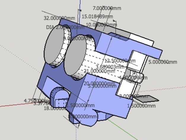
FPV Dual Camera Tilting Mount
thingiverse
The was created to solve a common problem encountered when flying a multirotor in first person video and with a HD flight recorder. When the multirotor is forward flight, it often leaves you with a screen full of the ground and not the forward view. Tilting the FPV cam brings the horizon and forward view into the frame, but a fixed tilt isn't optimal when coasting in level flight (which leads to a screen full of sky). Same holds true for the flight recording camera. A tiltable camera plate which can hold both FPV cam and flight recorder is the potential solution. This camera mount supports a Mobius keycam (dissected) and a 25x25 camera. Designed to fit on a mini-h multirotor frame (specifically the Nemesis). Add a 5g/9g servo for tilt control or camera stabilization via flight controller (ie. Naze32). NOTES: Actual pics to come. STLs will be provided for two piece print with through holes for the plate and mount hinge. The current STLs utilize a "captured" hinge design. This was created for personal use, but always open to suggestions for improvement. SketchUp file can be uploaded if requested. Added STLs for mount and camera plate with through holes for the hinge Frame specifications: 35mm height clearance 39mm min width clearance may require drilling a hole in the lower frame for mounting Works with: Nemesis Potential frames (untested): BAH v2.1, MXP230 Additional hardware required: M2x20mm screw for center M3x10mm screw and nut for side clamp Mobius extension cable (RMRC, GetFPV) Print instructions: The current STLs (with and without supports) are a one piece print. After printing, gently rotate the lower flange to loosen. Note that the camera plate is two part joined at the flat side by a 2.5mm tab. Keep this intact if possible. Assembly Prep: Mobius camera element will require dissasmbly from case and extended via a suitable cable. Expanding the center hole(s) on the top half of the camera plate with a M3 screw is optimal. Use the M2 screw to "self-tap" into lower camera plate. If necessary, use a longer M2 screw and hex nut. Thread M2x20mm screw, but don't tighten until both cameras in place (see below). Insert M3 screw on side clamp and thread hex nut slightly. Assembly instruction (flat side of camera plate faces forward): Insert Mobius camera element into lefthand side. The camera element should fit snugly in the provided opening. Note right-side screw tab should slide into slot. Insert 25x25 FPV camera fits on the righthand side so that its flush against the top camera plate Check that the the FPV camera housing is flush against the Mobius camera element screw tab. This actually provides security for the camera element along with the center screw. Secure the M2 center screw. If not using a hex nut, be careful not to strip the ABS. In actuality, this screw doesn't have to be very tight as the M3 screw provides the clamping of the 25x25 camera housing. Secure the M3 screw so that the FPV camera does not rotate. Careful not to break the tabs in the process. Mount to mini-h frame with M3 screw and hex nut. This may be easier before placement of cameras. Placement tips: Camera plate should be adjusted so that lenses are protected by leading edge of frame plates. Instructions Print instructions: The current STLs (with and without supports) are a one piece print. After printing, gently rotate the lower flange to loosen. Note that the camera plate is two part joined at the flat side by a 2.5mm tab. Keep this intact if possible. Assembly Prep: Mobius camera element will require dissasmbly from case and extended via a suitable cable. Expanding the center hole(s) on the top half of the camera plate with a M3 screw is optimal. Use the M2 screw to "self-tap" into lower camera plate. If necessary, use a longer M2 screw and hex nut. Thread M2x20mm screw, but don't tighten until both cameras in place (see below). Insert M3 screw on side clamp and thread hex nut slightly. Assembly instruction (flat side of camera plate faces forward): Insert Mobius camera element into lefthand side. The camera element should fit snugly in the provided opening. Note right-side screw tab should slide into slot. Insert 25x25 FPV camera fits on the righthand side so that its flush against the top camera plate Check that the the FPV camera housing is flush against the Mobius camera element screw tab. This actually provides security for the camera element along with the center screw. Secure the M2 center screw. If not using a hex nut, be careful not to strip the ABS. In actuality, this screw doesn't have to be very tight as the M3 screw provides the clamping of the 25x25 camera housing. Secure the M3 screw so that the FPV camera does not rotate. Careful not to break the tabs in the process. Mount to mini-h frame with M3 screw and hex nut. This may be easier before placement of cameras. Placement tips: Camera plate should be adjusted so that lenses are protected by leading edge of frame plates.
With this file you will be able to print FPV Dual Camera Tilting Mount with your 3D printer. Click on the button and save the file on your computer to work, edit or customize your design. You can also find more 3D designs for printers on FPV Dual Camera Tilting Mount.
