FPV Screen Enclosure
thingiverse
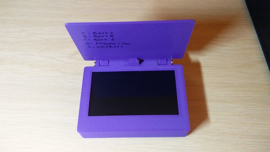
FPV screens are pricey for what they offer, so when I found an affordable FPV video system on Banggood, I decided to craft a custom case for it. This sleek package includes built-in batteries, a charger, receiver, XT60, and screen cover, making it easy to toss into my bag and pull out as needed without worrying about finding batteries or antennas. This innovative design features two primary components: one with an internal lipo battery and the other without. The case also boasts a screen cover, a flap holder to keep the screen open, and a back panel. The antenna is cleverly integrated within the case, ensuring reliable reception despite being nestled between a battery and metal screen. However, if you want to charge using the USB connector, be prepared for a slightly longer plug than usual. Important Note: You're working with built-in Lipos and charging capabilities. If you're not confident in your soldering or electronics skills, please don't attempt this project. Safety first – avoid blowing up your house! --- Required parts --- The screen and receiver board can be found here: https://www.banggood.com/RX5808-5_8G-48CH-FPV-Receiver-with-5-Inch-HD-Displayer-Snow-Screen-Monitor-DIY-For-FPV-Goggles-p-1309235.html A 5.8GHz FPV antenna is also required (you can opt for an SMA connector and solder it to the board or attach the antenna directly): https://www.banggood.com/2-PCS-65mm-2dBi-IPEX-IPX-FPV-Omni-Directional-Brass-Antenna-RG178-p-1213263.html?rmmds=search&cur_warehouse=CN Additional components include: * 1x switch: https://www.ebay.co.uk/itm/252106861027 * 2x lipo batteries (optional) with a thickness below 7mm: https://hobbyking.com/en_us/turnigy-nano-tech-950mah-1s-25-50c-lipo-pack-walkera-v120-x100.html * 1x voltage regulator (optional): https://www.ebay.co.uk/itm/401012912499 * 1x charging circuit (optional): https://www.ebay.co.uk/itm/112746837161 * An XT60 (optional) * 2x 3mm LED's of different colors (optional) * 2x 20mm M3 screws * 1x M2 3mm screw * 2x M2 6mm screws * 2x JST connectors (to connect the batteries) (optional) * Hot glue and a hot glue gun * Double-sided tape --- Assembly --- Prepare the electronics: * Remove the two LED's from the charging circuit. * Solder some wires to your two 3mm LED's and replace the surface mount LED's you removed from the charging circuit with them. * Solder the two JST connectors to the battery pads on the charging circuit. * Connect the screen power wire to the switch and the other end to the charging circuit output, then solder the other side of the switch and unconnected charging circuit output pad together. * Attach the XT60 to the voltage regulator input. Adjust the output voltage using the potentiometer on the regulator to around 4.5V to avoid damaging your screen! * Connect the voltage regulator output to the charging circuit input. * Remove the SMA connector cable and either solder the antenna directly or attach an SMA connector to the board. * Ensure all connections adhere to correct voltage polarities. Assemble the case: * Insert the screen into its slot (it should be a snug fit). * Secure the batteries on the back of the screen using double-sided tape. * Connect the ribbon cable to the screen connector on the main board and rest it on top of the batteries. * Push the XT60 into its holder and screw the switch into place. * Glue the charging board behind the USB opening (be careful, as alignment can be tricky). * Secure the LED's in their respective holes. * Attach the control board to the back panel. * Connect all connectors. * Close the case, designed to stay in place without screws. * Screw the screen cover onto the front of the box. * Slide the flap holder into place and secure it with a 3mm M2 screw. If your project sparks flames, drop it like hot coal!
With this file you will be able to print FPV Screen Enclosure with your 3D printer. Click on the button and save the file on your computer to work, edit or customize your design. You can also find more 3D designs for printers on FPV Screen Enclosure.