Frame for the Retro Chip Tester
prusaprinters
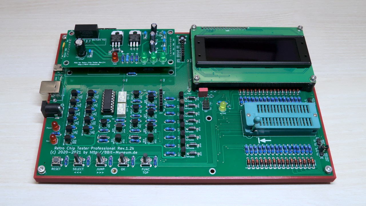
<p>This is a frame set for the <a href="https://8bit-museum.de/sonstiges/hardware-projekte/hardware-projekte-chip-tester-english/">Retro Chip Tester Professional</a> (RCT) by 8bit-museum.</p><p>The display frame is used to hold the display in place. I used an OLED display having mounting holes with 2.5mm diameter, but 3mm holes should work as well.</p><p><strong>Note: </strong>This design is prepared for a third printed part that is supposed to protect the switches from breaking off. You will find it here as soon as it is designed.</p><h3>Printing</h3><p>The display frame should be printed upside down, then it won't need any supports.</p><p>The base frame can just be printed as it is. Take care for warping though.</p><p>I used simple PLA, and a layer height of 0.2mm.</p><p>Before assembly, make sure that the printed parts will fit properly. I recommend to do a test print of the top 2mm of the base frame, in order to check that everything will sit properly and that there is no significant shrinking.</p><h3>Additional Material</h3><p>For the display frame:</p><ul><li>3x threaded inserts M2.5 x 4mm</li><li>2x threaded inserts M3 x 5.7mm</li><li>3x screws M2.5 x 6mm</li><li>1x screw M2.5 x 18mm</li><li>2x screws M3 x 6mm</li><li>4x washers M2.5</li></ul><p>For the base frame:</p><ul><li>4x threaded inserts M3 x 5.7mm</li><li>1x threaded insert M2.5 x 5.7mm</li><li>3x screw M3 x 6mm</li><li>3x washers M3</li><li>4x self-adhesive rubber feet (about 12mm diameter)</li></ul><p>You can replace the single insert M2.5 x 5.7mm with another M2.5 x 4mm insert if you're careful while inserting it. It should be flush with the top of the hole.</p><h3>Assembly</h3><p>Melt the M2.5 inserts into the top of the display frame. Do not use an insert for the top right hole!</p><p>On the bottom side of the display frame, both M3 inserts are melted into the opposing corners. A third corner cannot receive an insert, while that single other hole is still left open.</p><p>Now carefully screw the display frame onto the board from below using two M3 screws. Put the display on the board, then use the three M2.5 screws and three washers to fix it. The washers are important, as the screws are a bit too long, and would pull out the inserts when used without them. If you find some, you could also use M2.5 x 5mm screws without washers. Do not tighten the screws yet, but wait until the bottom frame is attached.</p><p>The long M2.5 screw (plus washer for optical reasons) is pushed through the upper right hole of the display, and will be used to connect the sandwich to the base frame.</p><p>On the base frame, melt the M2.5 insert into the top right corner. The other four inserts are melted into the remaining holes. After that, attach four rubber feet to the corners of the frame bottom.</p><p>Seat the board onto the base frame. It should fit perfectly. Now use the single display screw, and three M3 screws plus washers, to mount the board on the frame. After that, you can also tighten the display screws.</p><p>The hole next to the key switches is left open as of now. It is reserved for a third printed part that is supposed to stabilize the switches.</p>
With this file you will be able to print Frame for the Retro Chip Tester with your 3D printer. Click on the button and save the file on your computer to work, edit or customize your design. You can also find more 3D designs for printers on Frame for the Retro Chip Tester.