"Freak" Mechanical Clock
prusaprinters
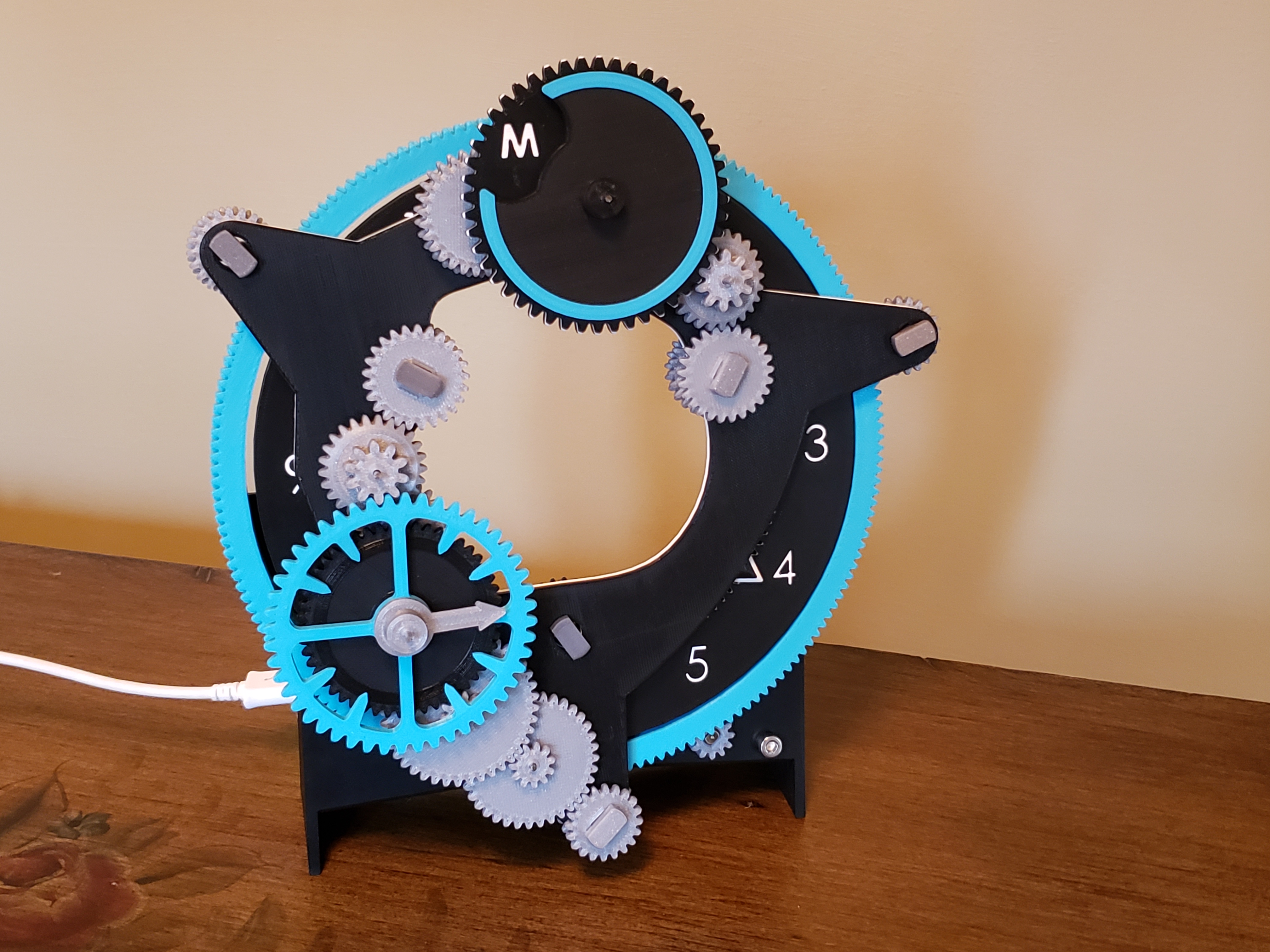
<figure class="image"><img src="https://media.prusaprinters.org/media/prints/69411/rich_content/ea630483-f587-495d-928a-7dfa54c07acd/freak-gif.gif#%7B%22uuid%22%3A%221b56bddb-f00f-4f49-af48-6f94397c7256%22%2C%22w%22%3A690%2C%22h%22%3A388%7D"></figure><p>The largest part is 182mm x 182mm, fits on a Prusa i3 (sorry mini). This is the first clock I've made and I went from proof of concept to fully printed model in like 2 weeks, so I apologize if anything is a little janky. Feedback is welcome.</p><p> </p><figure class="media"><oembed url="https://youtu.be/L93V5wHbFQM"></oembed></figure><h3>You will need:</h3><ul><li>1/16" steel rod (or 2mm just need matching drill bit) approx. 160mm (~7) in length + extra (<a href="https://amzn.com/B00FG1K5PI">https://amzn.com/B00FG1K5PI</a>)</li><li>28BYJ-48 stepper motor</li><li>driver/arduino - however you want to drive the stepper</li><li>short pieces of solid core wire or paperclip to hold the gears on the keypins</li><li>(optional) binder clips or similar to hold the gears on the shaft during assembly</li></ul><p>Just use whatever hardware fits, its not critical, but here is what I used:</p><ul><li>4x M3 x 12mm+ screws and nuts</li><li>2x M4 screws and nuts</li></ul><h3>Naming convention</h3><p>S(stage) [Stage # / name] [I for Input, O for Output, none is usually compound gear]</p><p>Some gears are used more than once and technically have more than one name. Also multiple stages can be on the same shaft (they spin at different speeds)</p><figure class="image image_resized" style="width:75%;"><img src="https://media.prusaprinters.org/media/prints/69411/rich_content/0b2a9122-7412-4163-9002-0c186eb9e913/s-diagram-anniote.png#%7B%22uuid%22%3A%22b7e0edd3-7679-4d32-a30d-91ffe83aefbd%22%2C%22w%22%3A1205%2C%22h%22%3A757%7D"></figure><p>Also see “Freak Clock asm.3mf” under extras for a 3d model of it all put together</p><p> </p><h3>Printing:</h3><p>I used manual color swaps (ie. M600) for the numbers and day of the week letters</p><p>I found that 0.1mm layer height for the gears made them work the best. Infill can be pretty low (~15%) on everything except for S0 and the ClockArm which you want higher (~30%) to avoid flexing.</p><ul><li>Clock face (internal gear) is printed face down</li><li>compound gear S7w (week face) is printed face down</li><li>compound gear S8w printed fine for me without supports</li><li>the base is printed face down</li><li>the keypins are printed on their flat side<br> </li><li>2x keypin S1 (SY on the week side uses the same one)</li><li>3x keypin S1 idler (SY idler)</li><li> </li><li>2x double gear S1 idler</li><li>2x double gear SY O</li><li>2x gear SY I</li><li>2x compound S6 (S6w)</li></ul><p>These can optionally be printing in a flexible material</p><ul><li>2x shaft-cap (probably of 2 different colors)</li><li>(optional) 2x base-shoe<br> </li></ul><h3>Steel Shaft Cut List:</h3><figure class="table"><table><tbody><tr><td style="background-color:#E0E0E0;"><strong>S#</strong></td><td style="background-color:#E0E0E0;"><strong>Length (mm)</strong></td></tr><tr><td>2</td><td>11.4 + </td></tr><tr><td>3</td><td>14.8</td></tr><tr><td>4</td><td>30 +</td></tr><tr><td>5</td><td>11</td></tr><tr><td>6</td><td>25 +</td></tr><tr><td>6w</td><td>20 +</td></tr><tr><td>7w</td><td>30 +</td></tr><tr><td>8w</td><td>12</td></tr></tbody></table></figure><p>(+) these can be longer, won't get in the way</p><p>all others cannot be more than ~2mm too long as they will get in the way</p><p>I like to leave the burr on the bottom end (and hammer them in from the bottom) to help the shaft stay in place. Try to de-burr the other end so the gear can slide on.</p><p> </p><h3>Assembly:</h3><p>You are going to want to test the fit of the shafts and the idler gears to the S0 ring gear before everything else.<br> </p><p>It is very important that S0 ring gear runs smoothly without resistance, but also holds onto the ClockArm. The internal clock face gear does not need to be as loose. The non-idler gears using keypins (S1, SY) should fit snug, so they rotate together, to reduce backlash. Keypins are held in wire/paperclip see pictures. You can put a little motor oil on the keypins if they keep sticking when it is all assembled.</p><figure class="image image_resized" style="width:50%;"><img src="https://media.prusaprinters.org/media/prints/69411/rich_content/48253065-862c-4d5d-9ed1-f9e8ce36ee6d/20210622_100856.jpg#%7B%22uuid%22%3A%2212d85135-3757-40fa-bb69-bd2dc0704ecb%22%2C%22w%22%3A3024%2C%22h%22%3A2556%7D"></figure><figure class="image image_resized" style="width:50%;"><img src="https://media.prusaprinters.org/media/prints/69411/rich_content/421785a5-42ec-48bf-b948-939d2b00c6d6/20210622_111222.jpg#%7B%22uuid%22%3A%22a6181b80-d095-4110-b5ad-5e616ff23ff4%22%2C%22w%22%3A3023%2C%22h%22%3A3431%7D"></figure><p><strong>To loosen:</strong></p><p>sand key pins or scale down (but not in length!)</p><p>sand inside of gears</p><p><strong>To tighten:</strong></p><p>scale up keypins (but not in length!)</p><p>use “tight” version of gears and sand down hole to fit<br> </p><p>The shafts need to fit tightly into the ClockArm and be perpendicular to the base. I just hammered them in using a gear like S6 as a guide. I've also included a drilling guide incase you need to drill out the holes. If they are too loose, you can glue them in with CA glue.</p><p>The gears need to spin freely on the metal shafts, mine worked fine right off the printer. You can drill them out with an 1/16" drill bit if needed (use the included drilling jig to make sure its straight.</p><figure class="image image_resized" style="width:50%;"><img src="https://media.prusaprinters.org/media/prints/69411/rich_content/dd241a42-87be-418b-9f80-ce63feaf58ac/20210622_103511.jpg#%7B%22uuid%22%3A%22eeec34bb-b72c-4c23-a8da-c4beab4f4055%22%2C%22w%22%3A3024%2C%22h%22%3A2177%7D"></figure><p><strong>The minute hand shaft from bottom to top:</strong><br>S4 O > S4 I (min hand) > S7 (min face) > min-hand > shaft-cap</p><p><strong>The day of the week hand shaft from bottom to top:</strong><br>S9w O > S7w > week-indicator > shaft-cap</p><p>The shaft caps are supposed to be press fit by hand, can be printed with flexibles. Just scale if needed</p><p> </p><h5>Set the Clock Alignment</h5><p>When you put the ClockArm on the ring, it locks in some of the positioning. It is best to set the time to 12:00 with the faces upright as you put in on for the first time. </p><figure class="image image_resized" style="width:50%;"><img src="https://media.prusaprinters.org/media/prints/69411/rich_content/0460cdb7-1e37-46aa-bc7e-db0277e41bbb/20210622_104322.jpg#%7B%22uuid%22%3A%22d9d345e8-882f-4de7-b4d2-261da97e9493%22%2C%22w%22%3A3023%2C%22h%22%3A2885%7D"></figure><h5>Align de-rotators (S7/S7w) instructions</h5><p>If the the faces somehow get out of alignment you can either pull the shaft-cap and gear off, and place it back the right way or disconnect the corresponding SY gear and spin S7(w) to the right position. </p><p>If the minute hand and hour “hand” (ClockArm) are out of alignment, disconnect SY or reassemble S4</p><h5>Clock setting instructions</h5><p>Disconnect S1 and rotate the ClockArm (might need to spin one of the gears by hand to do this) to the correct time. Or remove the motor gear and turn S0 for finer adjustment</p><p> </p><h4>Stepper Motor / Software</h4><p>The motor needs to spin at 5/6th RPM counter clockwise. Which would be -28.9628 steps if you use some thing like<a href="https://www.airspayce.com/mikem/arduino/AccelStepper/ConstantSpeed_8pde-example.html"> AccelStepper for Arduino</a> . I didn't have too much time to test the accuracy but you might need to adjust the motor speed slightly.</p><p> </p>
With this file you will be able to print "Freak" Mechanical Clock with your 3D printer. Click on the button and save the file on your computer to work, edit or customize your design. You can also find more 3D designs for printers on "Freak" Mechanical Clock.