FT-5 Enclosure Braces for 1/8in acrylic
thingiverse
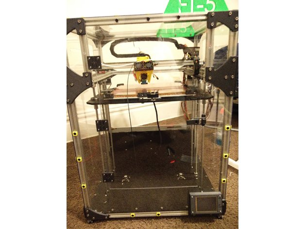
!Disclosure! I list measurements from my personal machine, BUT, a large but, your machine may differ than mine. Before chopping up your probably not cheap acrylic sheets, please do your own measuring and use mine as a reference. Okay I will try to describe this the best I can. First this enclosure is for The FolgerTech FT-5 and using a bowden setup with a e3d titan extruder. This may work with the stock extruder but not certain. Test it out and see :) First I will go over the Bill of Materials. BOM List: x1-Extruder Mount x3-Universal Hinges -----> http://www.thingiverse.com/thing:1209695 x1-Latch Assembly ------> http://www.thingiverse.com/thing:1844744 x6-T Brace x1-Left T Brace with Front Brace x1-Right T Brace with Front Brace x1-Left Corner Brace with Front Brace x1-Right Corner Brace with Front Brace x7-Right Corner Brace x6-Left Corner Brace x1-TFT32 Mount Rev 2 (If no TFT32, Then replace this part with x1 Left Corner Brace) x2-24in x 48in x 1/8in thick Sheet of Acrylic, PolyCarbonate, or Lexan x1-Extra T Nuts (need a lot) --------> https://www.amazon.com/gp/product/B019ZXUSY0/ref=oh_aui_detailpage_o06_s01?ie=UTF8&psc=1 x1-Extra Screws (Also need a lot) --------> https://www.amazon.com/gp/product/B01G9HUYJO/ref=oh_aui_detailpage_o06_s00?ie=UTF8&psc=1 x2-64 Screw Caps x2-Filament holders -------> http://www.thingiverse.com/thing:1813903 x1-16mm tube of >500mm for Spool holder To assemble this together first printout/purchase all of the parts pertaining to this build. It will also be extremely wise to purchase or use a jigsaw to cut the acrylic. Use metal blades. This is the unit I used but of course buy or use what you would like ------> http://www.homedepot.com/p/Ryobi-6-1-Amp-Variable-Speed-Orbital-Jigsaw-with-Speed-Match-JS651L1/203146378 First is to cut the acrylic to size. There is a specifc way to cut the parts and I cannot model them up currently so I will try to describe it the best I can for now. To start the measurements given can be off by roughly 1/16in - 1/8in maximum otherwise it will look like poo and not line up correctly. Use as many of the precut straight edges of the acrylic as you can. And only measure from precut edges. The goal is to figure out how to fit all the parts on the two sheets of acrylic you purchased. I did but I do not recall how I did. A quick sketch in CAD should do the trick for most. First the front of the machine is all a single piece. So cut out that shape. Should be about 28 1/4in x 21 1/4in. The Top is also a single piece. Size is 21 1/4in x 19 3/4in The sides and rear I divided into two pieces; the lower section and the upper section. These sections I designate are divided by the 2020 that mounts the linear rails for the y axis. So cut a piece to fit into each section while still covering have of the middle 2020 piece ( added photos to help with this) Do this for the sides and rear. The rear you need to stop short of the power supply and mks board bay. Sizes as follows: Sides: -Lower: 19 5/8in x 20 7/8in. -Upper: 19 5/8in x 7 3/8in Rear: -Lower: 21 /14in x 13 3/8in -Upper: 21 1/4in x 7 3/8in The Last piece will be the door. I have my door at 13in x 20in and centered on the front piece. DO NOT TRY TO ENLARGE ABOVE 13in WIDE, IT WILL NOT WORK. Really I do not advise enlarging it at all from my measurements. It is a perfect size and you do not have much room to enlarge it (height wise). Before final assembly two more things I will mention. First MAKE SURE YOUR PRINTER IS COMPLETELY SQUARED UP. Double check every measurement. I found my right y-axis linear rail was 1/8 inch lower than the left one. As well, remove the front middle 2020 section and cut it up. Note please make your own measurements for these as these can vary for each printer. My measurements are just for reference. x2-2 7/8in sections x2-6 1/4in sections Hopefully you can figure out where these fit into ;) Finally the assembly is fairly self explanatory. Lay the printer on its side so that the side you are working on it face-up. Makes a much easier platform to work on as it will not slide off or anything. Align each section in their designated area. Place the coordinating braces in their positions so that the holes are centered over the groove of the 2020. Mark each hole with a sharpy and drill them out. Match the drill bit size with the hole size in the braces. Do this step for all the braces. I recommend lightly mounting on corner and then finish the section. Makes it much easier to drill the rest without the acrylic sliding around. (Note: when drilling rule of thumb. Make sure you drill all the way through, and quickly. When you pierce the arcylic and the drill bit puts a mark on the 2020 it is very convenient to use those marks later to put the t-nuts in) The additional screws that will use the screw caps (yellow squares in my pictures) you can just guesstimate or measure where these go. Feel what you think looks right. This is just to make sure the acrylic is completely fastened onto the frame. When you get to marking up the top section, dont forget to drill out the slot for the motor wire to run though the acrylic. The Extruder mount uses that small slot in the stepper motor bay. As well don't forget to cut around the Spool mount holders which will need clearance since the mount on the inside of the FT-5 Frame (as pictured as well) Okay so you now have all the mounting holes drilled out. Next will be to cut out a clearance guide slot for the bowden tube. Take one of the upper side sections, and drill two holes spaced out to whatever you find will work. I think mine are 14 inches apart with a 1/2 bit. After those holes are drilled, use the jigsaw and cut from one hole to the other creating a slot like pictured. Another two holes to cut out are for the power plug as well as the usb for the mks board. Create slots the best of your ability. The final cutting that will be needed is the door section cut out of the front section. Center up the shape of the door to the best you can (I would measure it all out and outline it with sharpy on the acrylic first.) And cut that out. You should have no problems getting the rest of the enclosure sorted out (Door hinges and latch) mounted if you have made it this far. Any questions please ask me on here or in the FolgerTech Forum/ Facebook Group. Cheers! Print Settings Printer: FolgerTech FT-5 Rafts: Doesn't Matter Supports: Doesn't Matter Resolution: 0.200mm Infill: 85-100 percent Notes: So I used Carbon Fiber Enfused PLA. Almost two 0.8kg spools so beware. This is was with plenty of failed prints as well so 2 will be plenty. Other printer settings: Hotend Temp: 232 C Bed Temp: 64 C Wall thickness: 2mm I used 85 percent infill and the parts are extremely strong. You can go higher if you please but that is your choice. Speed is whatever you will like Exceptions: I printed the TFT32 Mount at 0.100mm and about 30mm/s for a good clean finish. You can do what you would like. This part does require supports.
With this file you will be able to print FT-5 Enclosure Braces for 1/8in acrylic with your 3D printer. Click on the button and save the file on your computer to work, edit or customize your design. You can also find more 3D designs for printers on FT-5 Enclosure Braces for 1/8in acrylic.