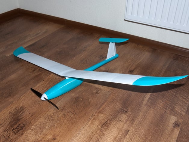
Fully 3D printed sailplane model. optimized for 0.2 nozzle (weight reduction)
thingiverse
It appears that the provided text is an article or a blog post from a DIY enthusiast who designed and printed various components for their drone, specifically the "Q500". Here are some tips on printing and assembly: **General Tips:** 1. **Printing Material**: Use PLA instead of ABS because it provides better layer adhesion. 2. **Layer Height**: Use a nozzle size of 0.3mm or smaller to ensure good detail in small features like wings, servos, or rudder parts. Layer height can be reduced as low as 0.1mm without sacrificing part stability. 3. **Print Speed and Temperature** \* Print at the maximum temperature allowed by your printer ( usually between 210-250°C). If it has a setting to set print speed per nozzle, do that - slow printing tends to result in stronger prints but higher layer adhesion, making layer shifting (inward) less likely. Lower temperatures will not give you more stable parts or layer adhesion as layer cooling rate and temperature are inversely proportional. 4. **Print with at least two perimeters to get enough shell material.** 5. **Wing printing** \* Wing parts require a special print technique - see next section below for hints on wing printing. **Wing Printing** 1. For maximum weight savings and good stability, reduce wall thickness of the part down to 0.2mm - no extra strength needed here. 2. Ribs or lattice-like structures do help provide extra support but increase printing time and filament used (thus adding mass) quite a lot - it is probably more convenient for this project not to have these extra details as your wings should fly fast, making air friction play a lesser role compared with drag created from having those supports printed. 3. You will want two pieces for the whole wing or, if you plan to get separate tip and base parts for better balancing, it is better to print tip parts in 5 pieces per side as there will be four more pieces on one part and printing would need longer times if not split this way. Use layer cooling. 4. Printing parts from center section toward both tips gives an option - a slight advantage of not using supports but may take quite a long time. 5. Use slicer to enable "Perimeter only" option, as well as " Top-Bottom layers", set it up to two so it gets three in total which is needed. **Tail printing** 1. Use standard settings, just print faster with good ventilation to reduce cooling effect that could otherwise shift printed part away from printer's heat bed. 2. Tail length may require a slight extension as well as increase in distance between horizontal stabilizer and fuselage; both adjustments should balance out the weight distribution. **Fuselage printing** 1. If your slicer can't make small pieces, consider printing all four side sections in one part (as the four supports would still prevent deformation of outer surface during first layers). In that case increase filament extrusion width and use thicker wall setting while reducing infill percent (or not have any - you won't gain strength with higher wall but lose due to added weight from it). Do this because printer temperature drops as you switch from hot print to hot pause mode, making outer layer not solid enough during cool period when only outer shell gets formed. 2. When printing side pieces that are attached via long hook shaped attachment which provides stability - print slower for those pieces as less chance of deforming or even breaking it while lifting part up due lower cooling effects at longer distances between first layers printed from nozzle head's hot core during cool phase in this printing technology ( FFF ) used with filament like PLA
With this file you will be able to print Fully 3D printed sailplane model. optimized for 0.2 nozzle (weight reduction) with your 3D printer. Click on the button and save the file on your computer to work, edit or customize your design. You can also find more 3D designs for printers on Fully 3D printed sailplane model. optimized for 0.2 nozzle (weight reduction).