Fully parametric & fully printable spool spindle and frame.
thingiverse
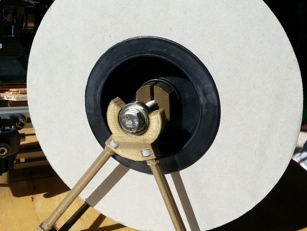
A fully printable spool holder is required for your 3D printer, utilizing only cable ties, bearings (608 size), and M8 hardware. The original design supports 1kg spools without issues. To create this spool holder, you will need to print several parts including bearing brackets, lower brackets, rods, and half spindles. Assembly is straightforward and involves using cable ties to secure the rods into place. For the spindle assembly, you'll need 608 bearings, M8 bolts, washers, and nuts. Simply follow the provided instructions and images for easy assembly of this sturdy and adjustable spool holder.
With this file you will be able to print Fully parametric & fully printable spool spindle and frame. with your 3D printer. Click on the button and save the file on your computer to work, edit or customize your design. You can also find more 3D designs for printers on Fully parametric & fully printable spool spindle and frame..