Gear generator for Solidworks (Straight / Helix / Herringbone)
thingiverse
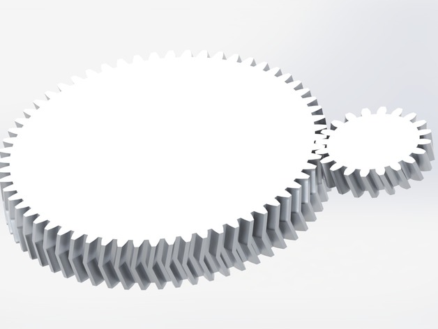
Pinion gear generator True involute curve profiled teeth - no spline approximation Customisable teeth, depth, module & pressure angle Configurable helix Herringbone capable See instructions for detailed info... Updates: V1 Initial Upload V1.1 Added offset option to allow for printing tolerances Changed top and bottom plane definition for right and left twist to be more consistent through new configurations Consolidated root extrude feature into tooth profile cut Added controls for offset amount and suppression state in design table to allow for 0 offset Renamed a few features V1.2 Added approximate profile shifting for gears below 20x Teeth Added mating profile for tangency mating of gears Added gear profile for gear ratio mate Adjusted how the herringbone is generated as it broke on some configurations Video Introduction This is a pinion gear generation part for solidworks with options for helical and herringbone tooth profiles. Using design tables within solidworks, you'll be able to customise as many pinion gear configurations as desired. There are some limitations with what can be generated, which are detailed with a brief description of each parameter below Customisation options Teeth - Integer value Number of teeth on the gear. This is minimum limited to about 10-12 teeth duer to the drastic change in tooth profile required if you want teeth quantities less than this. Module - Non-integer positive value The circumference reference pitch of each tooth. Usually a multiple of 0.25mm. Minimum printing value is about 1.5-2mm for a 0.4mm nozzle. Any less and your gear will have critical geometry smaller than you can reliably print. Pressure angle - Non-integer positive value The angle to the tangent where two mated gears mesh fully that the tooth engagement will follow. This is a standard at 20deg and should rarely be altered. Gear width - Non-integer positive value The gear width is the measurement between both circular faces of each side of the gear. In a herringbone configuration, this value is doubled. Helix angle - Non-integer positive value The helix angle is the angle of rotation with respect to the gears' axis. 0 degrees is a straight cut pinion gear, and 90degrees is an infinite number of twists and will probably crash your instance of solidworks! Right hand / Left hand helix - Boolean The right hand and left hand helix options dictate whether your helix angle will rotate clockwise (right hand) or counter clockwise (left hand) along the width of the gear. These options are chosen by unsuppressing either the "twist right" or "twist left" feature states in the design table. Both shouldn't be unsuppressed at the same time Herringbone tooth profile - Boolean The herringbone tooth profile option will literally mirror the helix pinion gear about the far-side circular face of the gear. The helix angle will then be reversed, and a herringbone tooth profile will be created. This profile is used by many extruders (wades being the most popular) as a herringbone profile will remove almost all axial load (not usually desirable) on the gear. Offset - Non-integer positive value The offset shown in the screenshot attached to this thing will reduce the tooth edges along the profile of the tooth, including the root of the tooth (the tip is not reduced with the offset parameter) by a dimension specified by this design table entry. I have not printed using this feature yet, but I can imagine you'd need a small offset of about 0.05 to 0.1mm to account for printing inaccuracies. This saves the need to sand each tooth to size after printing. Options shown in yellow in the design table screenshot are the only values to be changed by the user. The other values should be copied to all configurations as they are calculated within the design table. Design details 3D printer co-ordinates Make sure, when exporting the STL from solidworks, you open the options panel in the "Save As..." dialog, and use the "3D Printer coords" coordinate system as your coordinate reference. Otherwise, machining coordinates will be applied, and your gear will have to be rotated on your slicer's bed. Saves annoyance. Trust me. Meshing Reference Within the model, the pinion gear has a specific diameter circle about the axis that should be used when mating gears together tangentially. I keep the "Meshing reference" sketch visible when using these gears in a solidworks assembly as it makes it easy to mesh gears with the mate tool. Rotating each gear prior to making a "gear mate" is required by hand unfortunately. I can't think of an elegant way to define this in a sketch and allow gears to be rotated in an assembly. Other All measurements are in mm. Sorry yanks! (although easily changeable) I am still yet to print one of these gears, so please, if you make one, post a "made" submission! I've added a pair of small herringbone gears STL's for anyone to print as a tester. Settings for these gears are provided in the solidworks part as "Demo R" and "Demo L". Both should mesh along the entire tooth profile of both gears. Note the licensing of the tool. Please attribute where this tool has been used. Thanks
With this file you will be able to print Gear generator for Solidworks (Straight / Helix / Herringbone) with your 3D printer. Click on the button and save the file on your computer to work, edit or customize your design. You can also find more 3D designs for printers on Gear generator for Solidworks (Straight / Helix / Herringbone).