Gearbox with adjustable ratios
thingiverse
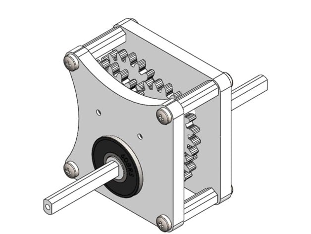
I had a need to slowly move a pinion gear on a rack. Using a DC Motor controller with my small hobby motors to lower the RPM, I had to sacrifice torque. A gearbox was my solution. This is a generic but customizable gearbox, that exposes (via arcs in the face) two sides of the "driving" gear so that you can "engage" your motor. Your motor can be attached via your bracket (that you print), through the mounting holes on the faces. A bracket for a "DC 3-12V Gearmotor for ARDUINO Robot Smart Car" has been included. https://www.youtube.com/watch?v=nSY02jBna0w Instructions Materials: 8 off 4G x 9mm self tapping button head screws. 2 off 2mm wires 25mm long (thin coat-hanger wire). 2 off 608 skate bearings (OD 22mm, ID 8mm, W 7mm). Print one of each face. Print 4 of 16.5mm spacers. Print one axle. Print one of each bearing spacer. Print 2 of 4.5mm gear spacer. Print 3 of 1mm gear spacer. Print 1 of keyed single gear. Print 3 of double gears. Print 1 of MotorGear. Optional: Print 1 of Motor bracket (if the included one does not suit, design and print your own). Optional: hardware for mounting motor to bracket (2 x 25mm M3 screw and nut for 1 supplied). Assembling the gearbox: Drill "out" the 2mm holes in the faces, gear spacers and gears. Lightly file the rough print surface on all parts. Put a dab of petroleum jelly/grease on touching surfaces. Press 1 off skate bearing into each face, flush with non-bed surface of print. Press 2 off 2mm wires into 2mm holes in rough side of square face. Fasten 1 off 16.5mm spacer in each corner with 1 off 4G x 9mm screws. The spacers will be on the same side as the wires. Position face with wires up, and bearing to the top on a flat surface. Insert 1mm gear spacer on right-side wire. Insert double gear on right-side wire, small gear down. Insert 4.5mm gear spacer on left-side wire. Insert double gear on left-side wire, small gear down, meshing gears of left and right side. Insert 1mm gear spacer on right-side wire. Insert double gear on right-side wire, small gear down, meshing gears of left and right side. Insert 4.5mm gear spacer on left-side wire. Insert the remaining face onto the two wires, with the arc's to the right and bottom. Fasten the 4 corners with 4G x 9mm screws leaving about 0.5mm gap from face to spacer. Prepare the single gear, axle, bearing spacers so they are a firm but adjustable fit; pull them apart. Insert the keyed single gear resting and centred on the bottom bearing, meshing with the lower small gear. Turn the gearbox housing on its left side. Pass the axle through the bearings and the single gear in there current positions. From the right pass the smaller bearing spacer over the axle and into the bearing, flush with the outside of the bearing. From the left side pass the larger bearing spacer over the axle and into the bearing, flush with the outside of the bearing. The thinner side will be inside the gearbox. Test by rotating the "driving gear" (the one closest to the arcs) with your fingers. Tighten or loosen one side of the screws to suit. Assembling the motor mount: Carefully push the axle so it is flush with the bearing on the square side. With the square face down and bearing to the top, remove the lower 2 corner spacers completely. Insert the motor mount into the face corners, with flat face up. Fasten with 4G x 9mm screws (removed). Place motor gear onto motor axle (side without a dimple). Line up holes on motor with holes in motor mount, engaging the gears. Fastem M3 scews through motor and mount with nuts in mount slots. Carefully power up and tweak M3 and 4G screws to suit. Adjusting ratios with supplied parts: Remove or add pairs of double gears. Create new corner spacers to new width using CornerSpacerMM.dxf (extruded). Print 4 corner spacers. Replace 2mm wires with ones adjusted to new width. Assemble as above. Adjusting ratios with custom parts: Work out desired configuration with paired gears, keyed gear and motor gear needing to match tooth specs. Print paired gears with large gear extruded 3mm, the small gear extruded a further 4mm and 2mm central hole cut. Print keyed gear at 3mm extrusion and the axle vector (smallest curve in MotorGearMM.dxf) cut central. Print the motor gear with the gear extruded 3mm to suit your motor (DXF included as a guide). Treating the bearing hole as fixed work out new positions of new 2mm wire holes. Print both faces using the supplied DXF's extruded to 5mm. The 2mm wire holes will need to be moved to the new layout (#4). Assemble as above.
With this file you will be able to print Gearbox with adjustable ratios with your 3D printer. Click on the button and save the file on your computer to work, edit or customize your design. You can also find more 3D designs for printers on Gearbox with adjustable ratios.