Geeetech A10 Belt Drive Extruder
thingiverse
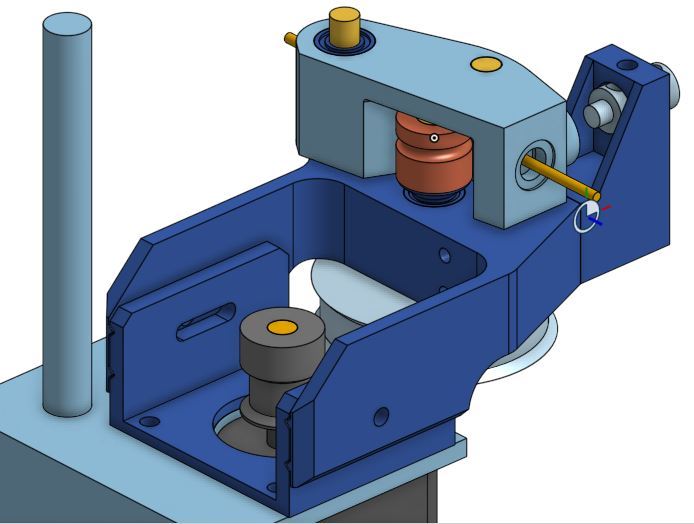
Why a belt driven extruder: - • If you observe extruder hob gear movements during normal operation, it is clear that many of the movements are very small and likely to be approaching the angular resolution of the stepper motor • Adding a gear/belt reduction of approx. 3.75 between the stepper and the hob increases the stepper movement by that factor and can only help with this resolution issue. • With very small movements backlash is completely un-acceptable. Gears have backlash, tight belts have no backlash - QED. • Marlin ‘linear pressure’ feature appears to have good benefits but does place even more emphasis on good extruder control/resolution. This design is the culmination of many iterations and should go together and work with no issues. My experience is that at least 3 iterations are required before a workable product is achieved and this has had many many more than that. The Guide Arm is the key element and this is derived from a published Thingiverse item. It is printed at 0.1mm layer height and orientated as in the stl. No supports are required. Most of the design work was completed using ‘Onshape’ and the following link https://cad.onshape.com/documents/b359a8b1d095f72d54029ff8/w/28d62f2730310813344fd82a/e/9f02cc14353ee78e1b75055d will give interested parties access to the design files. Use Alt+right mouse to manipulate the image. Assembly : - Body o Clean up – particularly sliding surfaces o Partially tap M5 and M3 holes – untapped part will lock threads o Insert two MR105 bearings o Screw in a cut down M5 bolt as the pivot for the guide arm. 15mm threaded, 26mm non-threaded. o Securely fix the Spring Mount with two M3 screws. Mount-Slider o Clean up – particularly sliding surfaces Guide Arm o Clean up o Use 2mm drill to clean out the through hole o Insert two MR105 bearings o Partially tap M5 hole – untapped part will lock threads o Insert pinch MR105 using cut down M5 bolt to secure. Bolt should have a non-threaded section o Thin down a M6 nut and use to secure the Bowden fitting. o Super glue a small piece of Bowden tube as an input guide Hob/60T Wheel o Lock 60T wheel to one end of 75mm long 5mm rod. o Place one spacer next to 60T wheel. o Insert into base. o Place hob spacer and hob on top. Firmly press together and securely fix the hob. Ensure all grub screws are very tight. If necessary file small flats on the rod. o Check that it rotates freely. Install the Guide Arm o Place a spacer next to the body/MR105 o Position the guide arm o Place another spacer and then the cap. If necessary glue the cap in place. Note Guide Arm must be free to move up and down to allow it to align with the filament and hob. o Insert the spring and plug, and secure with an M3 bolt On the Geeetech A10 o Manipulate the belt, body assembly and 16T wheel into place o Fix the Mount-Slider and stepper with slightly longer M3 screws o Use two M3 screws, nuts and washers to lock the sliding parts o Temporarily use a screwdriver lever to tighten the belt, then lock the slider o Finally adjust the height of the 16T wheel to ensure that the belt is centered, then securely lock the 16T wheel o Ensure everything is tight and then test the extruder with a piece of filament o The extruder direction will be reversed. Either reverse the stepper connections or better still reverse the direction in ‘configuration.h’ before compiling and downloading o Adjust the extruder steps/mm to approx. 390. Fine tune by extruding 100mm and re-adjusting 0.2mm layer – Body, Mount-Slider, Spring Mount 0.1 mm layer – Guide Arm, Hob Spacer, Plug, Push Fit Cap and Spacer All prints – 3 shells and 10% infill (lines) and no supports are required.
With this file you will be able to print Geeetech A10 Belt Drive Extruder with your 3D printer. Click on the button and save the file on your computer to work, edit or customize your design. You can also find more 3D designs for printers on Geeetech A10 Belt Drive Extruder.