Geeetech i3 Pro C inductive sensor mount
thingiverse
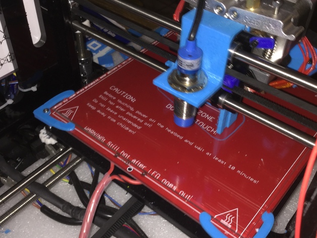
Update Nov 4, 2017 I've added a 3D Touch version of this mount. Check it out! "3D Touch sensor Mount Geeetech I3 Pro C(B) mounting" Inductive sensor mount for Geeetech Prusa I3 Pro C The mount uses the existing top X axis mount screws. It mounts on the rear of the X axis and rests on the top bearing. New Photo added. Shown without aluminum foil under the glass - not needed anymore. If you print this, please post a picture on the 'I've made one'. Thanks! Post-Printing Problems getting auto level working First, I had the wrong sign on the offset. This caused chaos in the centering, auto leveling, and Slic3r. Should have been -51 not 53 (remeasured and found it to be 51mm). Secondly, comes the confusing part of bed_position verses offset. Yes, they interact with each other. I've made notes on how it calculates the position. I hope this helps. This took the longest time (hours) as every change I had to upload the new changed firmware moving only one point at a time to see what changed. Then I used the following codes most often to help in troubleshooting: G28 X0 Y0; Home X and Y only to the stops. This prevents homing to the center. G29; auto level command. M114; to print out current printer position. (Repetier-Host also echoes the position in the bottom window) G1 ?; where ? = axis to move, and = to what position. (example G1 X50 moves X axis to 50) Software using: Repetier-Host V1.6.2 to enter G codes manually and to have the cursor over the Emergency Stop - just in case (used many times) After tweaking the numbers for the offset, and probe_bed_positions I finally had the auto level going to the positions I wanted. But a G28 (home) sent the extruder to the center and beyond the back of the printing bed. 3rd correction; I found Z_safe_homing. and tried subtracting from the safe_homing_Y-Point. It worked! With some tweaking I settled on -20 in the X and -100 in the Y. First print with the new set up. Centered in the bed, Slic3r works perfectly. How I Designed This My design is based on a sensor mount for Geeetech Prusa I3 Pro C The mount uses the existing top X axis mount screws. It mounts on the rear of the X axis and rests on the top bearing. Next step: Things I've learned While this sensor mount works, the sensor is a bit far away from the extruder. This prevents doing a 9 point auto level. I'm looking at ways to redesign it. It will be similar to this one. I also believe the extruder can be mounted closer to the centerline of the axis. (Drilling holes closer will do it). These two 'updates' should allow for a closer spacing and possibly 9 point auto level. I also found that my glass plate was being warped by the clamps, wires, and aluminum foil. Corrections. I flipped the heating bed over (not how any pictures I have seen from Geeetech). Then I made some great glass clips. Kudos to the author (I'll take pictures later and officially thank them). Doing this has allowed me to get rid of the aluminum foil, as the 8mm sensor can now sense the heating bed! And the clips mean I have a full bed to print on now - nothing to run into. I hope this posting gives you the information that you need to get your auto level operating. Next step: Things I've learned ... continued My glass bed is just not level. If I try to level with the leveling knobs, it seems to warp from opposite corners. The fix for now - is to not have the bed perfectly level and use the leveling knows to keep the glass plate from warping. This caused the z axis to correct about 1/2 a turn from the front to the back but it seems to be working well. I have taken the printer apart and verified that the x-y mounting plate is perpendicular to the z axis and close to level in all positions. It is just when the glass plate gets attached things go haywire and the glass plate warps. Could be a bad glass plate? Research shows others have that problem. Change to metal? I haven't had much problem with my prints coming off the glass. I hear a lot of problems with metal plates. For now, I think I will be ok with the 'having to not level fully' and just have the auto level correct for any flaws. Hope this helps
With this file you will be able to print Geeetech i3 Pro C inductive sensor mount with your 3D printer. Click on the button and save the file on your computer to work, edit or customize your design. You can also find more 3D designs for printers on Geeetech i3 Pro C inductive sensor mount.