Gehäuse/case für ESP32- und ESP8266-Boards, Raspberry Pi Zero, Raspberry Pi pico, ESP32-CAM, diverse Sensoren und Displays
thingiverse
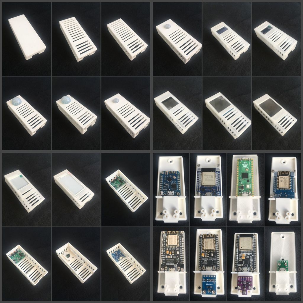
Gehäuse für ESP32- und ESP8266-Boards, Raspberry Pi zero, Raspberry Pi pico, ESP32-CAM, diverse Sensoren und Displays PDF-Beschreibung --> https://cdn.thingiverse.com/assets/59/50/ab/a7/36/NodeMCU-Case.pdf Freue mich über jeden Remix und Make! Case for ESP32- and ESP8266-Boards, Raspberry Pi zero, Raspberry Pi pico, ESP32-CAM, different sensors and displays PDF-description --> https://cdn.thingiverse.com/assets/59/50/ab/a7/36/NodeMCU-Case.pdf I'm happy about every remix and make! *** english description below *** ** Änderung 21.03.2021 ** PDF-Dokumentation aktualisiert STEP-Files für jedes Ober- und Unterteil eingefügt (ZIP-File) ** Änderung 14.03.2021 ** 1 Unterteil für AI-Thinker ESP32-CAM-MB hinzugefügt 4 Oberteile für AI-Thinker ESP32-CAM-MB hinzugefügt 1 Oberteil für AI-Thinker ESP32-CAM hinzugefügt (weitere folgen) ** Änderung 28.02.2021 ** Unterteil für Raspberry Pi Zero hinzugefügt Oberteil für Waveshare 2,13 Zoll e-Ink hinzugefügt Fusion 360 File hinzugefügt ** Änderung 27.02.2021 ** Kugelkopfhalterung hinzugefügt; Details --> https://www.thingiverse.com/thing:4777756 ** Beschreibung ** 3D-Druckvorlagen für Gehäuse in denen unterschiedliche ESP32- und ESP8266-Boards, der Raspberry Pi pico sowie verschiedene Sensoren und Displays verbaut werden können. Die Gehäuse bestehen aus je einem Unterteil und einem Oberteil, in denen jeweils unterschiedliche Boards, Sensoren und Displays verbaut werden können. Die Gehäuse werden einfach zusammen gesteckt. Bei meinem Drucker ist die Passgenauigkeit sehr eng. D.h. einmal zusammen gesetzt lassen sich die Gehäuse nur mit einem Holzbeitel oder scharfen Messer wieder öffnen. Die Größe der Gehäuse ist ursprünglich darauf ausgelegt, dass alle Verbindungen gelötet werden und nicht mit Jumperkabeln gesteckt werden. Die Gehäuse wären für die Benutzung von Jumperkabeln höher geworden. Aus Feedback habe ich mitbekommen, dass Jumperkabel bentutz werden. Deshalb gibt es von allen Oberteilen eine hohe Version, die 5mm höher ist. Hier sollte Jumperkabel passen. Die Zuführung des USB-Kabels ist verdeckt auf der Unterseite der Unterteile. Kleine Sensoren werden über dem Anschluß für das USB-Kabel verbaut. Gerade für Temperatur-Sensoren habe ich rausgefunden, dass diese möglichst weit von der WLAN-Antenne entfernt sind, da sonst die Ungenauigkeiten zu groß sind (weiß der Henker warum). Die Bohrungen für die Sensoren in den Unterteilen sind für BME280, BME680 und BH1750 vorgesehen. Sicher lassen sich auch weitere Sensoren hier anbringen. Mit diesen drei Sensoren habe ich es ausprobiert. Alle Boards, Sensoren und Displays werden mit M2x5mm Schrauben befestigt. Die Bohrlöcher beinhalten ein Gewinde. Wenn ein Board oder Sensor keine Bohrlöcher hat, so gibt es Montagestücke, mit denen diese befestigt werden können. Es gibt ebenfalls Montagestücke, wenn die M2x5mm Schrauben zu lang sind. Die Montagestücke dienen dann als Distanzstücke. Die Löcher im Unterteil zur Wandbefestigung sind für 3mm Holzschrauben ausgelegt. Die Versenkung für den Schraubenkopf hat einen 45° Winkel. Es gibt ein Unterteil ohne Bohrlöcher für Boards. Habe gelesen, dass einige Leute die Boards mit doppelseitigem Klebeband aufkleben. Für den Druck habe ich eine 0,4mm Düse/Nozzle und eine 0,1mm Schichtdicke/Layer benutzt. Die Unterteile werden richtig herum mit 15% Stützstruktur/Support gedruckt. Die Oberteile sind für den Druck um 180° auf den Deckel zu drehen. Diese werden dann ohne Stützstruktur gedruckt. Ein Export der Konstruktion aus Fusion360 als DXF-Datei ist bei den Downloads dabei. Die Liste der STL-Files und deren Kombinationsmöglichkeiten sind in anhängender PDF-Datei aufgeführt. Es gibt Unterteile für folgende Boards: - D1 Mini V2 - D1 Mini V3 - NodeMCU Lua Amica - NodeMCU Lua Lolin - ESP32 NodeMCU - ESP32 D1 Mini - Raspberry Pi pico - Raspberry Pi zero - Raspberry Pi zero W - Raspberry Pi zero WH Folgende Sensoren werden untersützt: - BME280 - BME680 - BH1750 - HC-SR501 - PIR Wemos Lolin - AM312 Folgende Displays werden unterstützt: - ST7789 1,54 Zoll TFT IPS LCD Display Modul 240x240 SPI - 0,96 Zoll OLED I2C Display 128 x 64 Pixel - Waveshare 1,3 Zoll LCD Display Modul, IPS Screen, 240x240 HD Auflösung, SPI Interface (SKU 15867) - Waveshare 200x200, 1,54 Zoll E-Ink Display Modul, SPI interface (SKU 12955) - Waveshare 200x200, 1,54 Zoll E-Ink Display Modul, SPI interface, 3-farbig (SKU 13338) - Waveshare 1,8 Zoll LCD Display Modul, 128x160 Pixel, SPI interface (SKU 13892) - Waveshare 250x122, 2.13 Zoll E-Ink display HAT for Raspberry Pi (SKU 12915) - Waveshare 212x104, 2.13 Zoll E-Ink display HAT for Raspberry Pi, rot/schwarz/weiß 3-farbig (SKU 13448) - Waveshare 212x104, 2.13 Zoll E-Ink display HAT for Raspberry Pi, gelb/schwarz/weiß 3-farbig (SKU 14226) Folgende Kameras werden unterstützt: - AI-Thinker ESP32-CAM-MB mit normalem Objektiv - AI-Thinker ESP32-CAM mit normalem Objektiv *** english version *** **Update 03/21/2021** PDF documentation updated STEP files inserted for each upper and lower part (ZIP-file) **Update 03/14/2021** 1 lower part for AI-Thinker ESP32-CAM-MB added 4 upper parts for AI-Thinker ESP32-CAM-MB added 1 top part for AI-Thinker ESP32-CAM added (more to come) **Update 02/28/2021** Added lower part for Raspberry Pi Zero Top part for Waveshare 2.13 inch e-Ink added Fusion 360 file added **Update 02/27/2021** ball point added; details --> https://www.thingiverse.com/thing:4777756 **Description ** 3D printing templates for housings in which different ESP32 and ESP8266 boards, the Raspberry Pi pico and various sensors and displays can be installed. The housings each consist of a lower part and an upper part, in each of which different boards, sensors and displays can be installed. The housings are simply plugged together. The accuracy of fit is very tight on my printer. That means, once put together, the housing can only be opened again with a chisel for wood or a sharp knife. The size of the housing is originally designed so that all connections are soldered and not plugged with jumper cables. The housings would have been taller for the use of jumper cables. From feedback I heard that jumper cables are used. That is why there is a high version of all tops, which is 5mm higher. Jumper cables should fit here. The feed of the USB cable is covered on the underside of the lower parts. Small sensors are installed over the connection for the USB cable. For temperature sensors in particular, I found out that they should be as far away from the WiFi antenna as possible, otherwise the inaccuracies are too great (the hangman knows why). The holes for the sensors in the lower parts are intended for BME280, BME680 and BH1750. Other sensors can also be attached here. I tried it with these three sensors. All boards, sensors and displays are attached with M2x5mm screws. The drill holes contain a thread. If a board or sensor has no drill holes, there are mounting pieces with which these can be attached. There are also mounting pieces if the M2x5mm screws are too long. The mounting pieces then serve as spacers. The holes in the lower part for wall mounting are designed for 3mm wood screws. The countersink for the screw head has a 45 ° angle. There is a lower part without drill holes for boards. Read that some people tape the boards with double sided tape. For the print I used a 0.4mm nozzle and a 0.1mm layer thickness. The bases are printed the right way up with 15% support. The upper parts must be rotated 180 ° on the lid for printing. These are then printed without a support structure. An export of the design from Fusion360 as a DXF file is included with the downloads. The list of STL files and their possible combinations are given in the attached PDF file. There are lower parts for the following boards: - D1 Mini V2 - D1 Mini V3 - NodeMCU Lua Amica - NodeMCU Lua Lolin - ESP32 NodeMCU - ESP32 D1 Mini - Raspberry Pi pico - Raspberry Pi pico - Raspberry Pi zero - Raspberry Pi zero W - Raspberry Pi zero WH The following sensors are supported: - BME280 - BME680 - BH1750 - HC-SR501 - PIR Wemos Lolin - AM312 The following displays are supported: - ST7789 1.54 inch TFT IPS LCD display module 240x240 SPI - 0.96 inch OLED I2C display 128 x 64 pixels - Waveshare 1.3 inch LCD display module, IPS screen, 240x240 HD resolution, SPI interface (SKU 15867) - Waveshare 200x200, 1.54 inch E-Ink display module, SPI interface (SKU 12955) - Waveshare 200x200, 1.54 inch E-Ink display module, SPI interface, 3-color (SKU 13338) - Waveshare 1.8 inch LCD display module, 128x160 pixels, SPI interface (SKU 13892) - Waveshare 250x122, 2.13inch E-Ink display HAT for Raspberry Pi (SKU 12915) - Waveshare 212x104, 2.13inch E-Ink display HAT for Raspberry Pi, red / black / white 3-colored (SKU 13448) - Waveshare 212x104, 2.13inch E-Ink display HAT for Raspberry Pi, yellow / black / white 3-colored (SKU 14226) The following cameras are supported: - AI-Thinker ESP32-CAM-MB with normal lens - AI-Thinker ESP32-CAM with normal lens
With this file you will be able to print Gehäuse/case für ESP32- und ESP8266-Boards, Raspberry Pi Zero, Raspberry Pi pico, ESP32-CAM, diverse Sensoren und Displays with your 3D printer. Click on the button and save the file on your computer to work, edit or customize your design. You can also find more 3D designs for printers on Gehäuse/case für ESP32- und ESP8266-Boards, Raspberry Pi Zero, Raspberry Pi pico, ESP32-CAM, diverse Sensoren und Displays.