Glowing Demon Core Lamp
prusaprinters
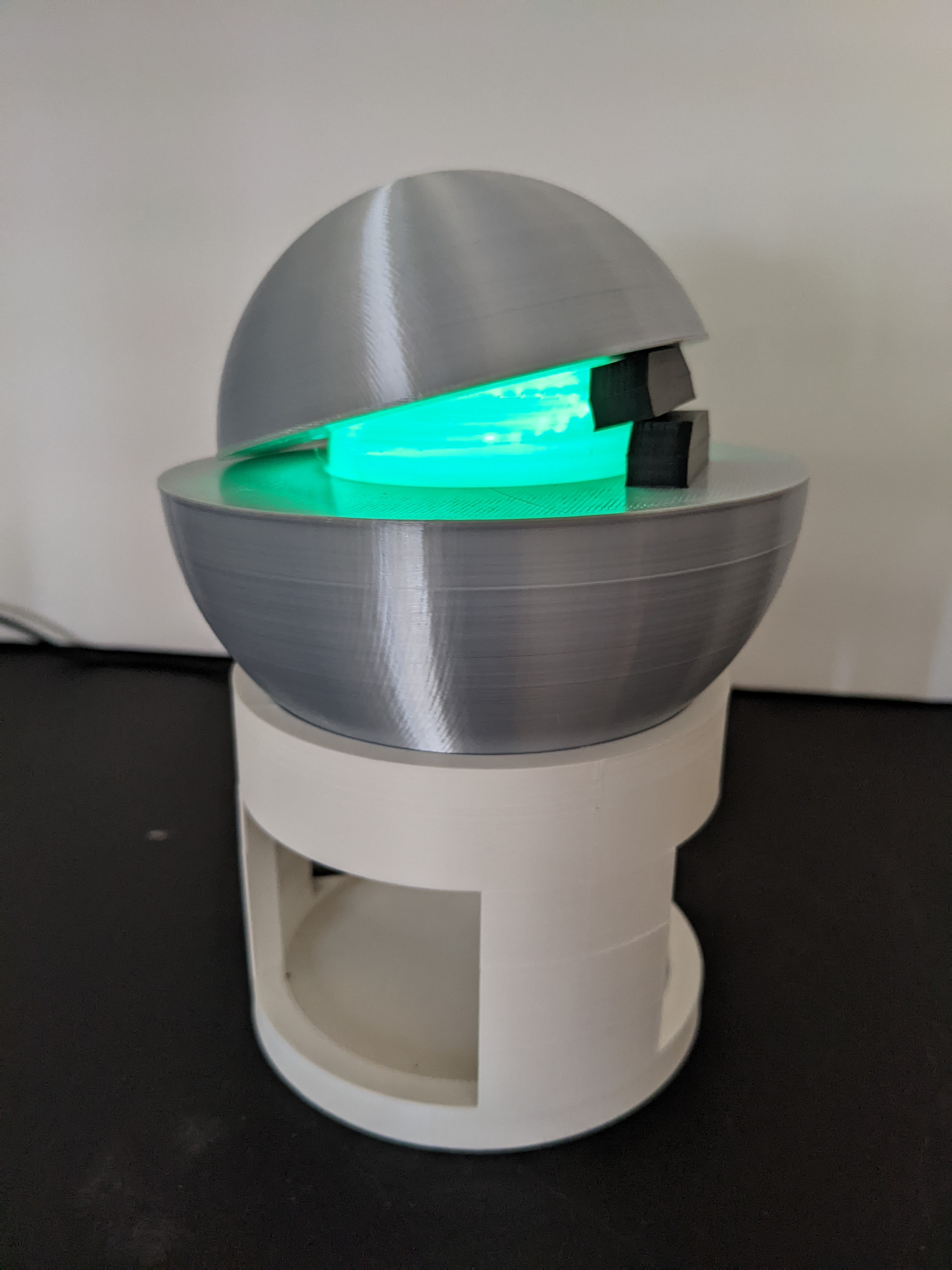
<h3>Want one of these but don't want to print it yourself? I sell them on Etsy too! <a href="https://www.etsy.com/listing/1270013702/demon-core-usb-lamp">Check them out here.</a></h3><p>This is a design for a lamp that looks like a demon core! A safe way to enjoy that blue radioactive glow without the danger! Just keep screwdrivers well away from it…</p><p>All of the CAD files are on Onshape if you'd like to modify this to fit a different LED/switch/USB cable/etc.! <a href="https://cad.onshape.com/documents/ca4a12e391678e53c6fd8b8f/w/52dd19ca4949cca1518a10d6/e/91b3e1b2fb0b79b3d23de57d">You can view the CAD document here.</a></p><h3>Printing Instructions</h3><p>I print all the files using a 0.6mm nozzle. A 0.4mm would work just fine too.</p><h5>core.stl</h5><p>The trickiest part to print is the core, which needs to be as thin as it is to allow light to shine through. However, this means that the top of the core doesn't have a lot of support so it could turn out a bit spotty on the top. However, using a 0.6mm nozzle and 0.2mm layer height allowed me to print it perfectly without any spottiness on the top. Your mileage may vary! It might take a few tries. My favorite filament to use for this part is <a href="https://coex3d.com/products/aqua-blue-pla">Coex Aqua Blue PLA</a>. It looks gorgeous with the LED shining through and has the perfect color.</p><h4>bottom_shell.stl and top_shell.stl</h4><p>For these parts, I used <a href="https://us.polymaker.com/products/polylite-silk-pla?variant=40302810890297">Polymaker PolyLite Silk Silver PLA</a>. The silver sheen comes out perfect and makes it look like metal without any postprocessing (I actually had someone ask if it was machined aluminum when they saw photos of it!)</p><p>These parts shouldn't be too tough to print, but you can still sometimes end up with spottiness at the tops of the hemispheres. You might need to play with print settings a bit for these too. I print them at 0.2mm layer height and 20% infill and end up with some slight spotiness at the top of the bottom shell piece, but that isn't very visible in the final product so I don't worry about it too much.</p><h4>center_insert.stl</h4><p>This is the part that the LED mounts to and that allows the USB cable to run down. I print it in the same Silk Silver PLA as the shell pieces, but since it's not very visible you can probably print it in whatever color you wish if you don't want to use up the Silk Silver filament on these pieces.</p><h4>stand_bottom.stl, stand_top.stl, glue_jig.stl</h4><p>These parts are the easiest to print out of the bunch. The angled spot in the top stand where the bottom shell rests has a slight overhang but it should be doable in most cases. The parts are glued together, and glue_jig.stl can be placed around the stand bottom, with the stand top pressed into place with glue on the bottoms of the legs in order to keep everything aligned. Once the glue has set up enough, you can remove the jig. I print the stand pieces in <a href="https://coex3d.com/products/white-pla">Coex White PLA</a> but any white PLA will work. Or any color you want really.</p><h4>spacer.stl</h4><p>This piece is used to prop up the top shell to allow it to sit in any orientation you wish to show off the glowing core! An extremely easy part to print, settings shouldn't really matter for this. I used <a href="https://coex3d.com/products/black-pla">Coex Black PLA</a> but of course, any black filament will work just fine (or, again, any color you wish!).</p><h3>Electronics</h3><p>The way I've designed this is meant to be USB powered, using a <a href="https://www.dollartree.com/self-adhesive-led-push-lights/269818">Dollar Tree push light</a> as the LED source. If you pry them open you can harvest the LEDs inside. The anode and cathode (positive/negative) ends of the LED module are marked on the silkscreen which helps.</p><p>The bottom shell also contains a cutout for a switch, specifically <a href="https://www.amazon.com/dp/B07WW3WW3F">these sorts of big chunky toggle switches</a>.</p><p>The LED module mounts to center_insert.stl with glue, with pins in the print to align with the holes in the LED modules. The USB cable goes down through a slot in the insert part, which is designed for a USB cable ~3mm in diameter.</p><p>In total, the electronic components you'll need are:</p><ul><li>Switch</li><li>USB cable (with the B end removed so you can wire it up. Also snip off any wires that aren't 5V/GND)</li><li>22Ω Resistor (1/4W is fine)</li><li>LED Module</li></ul><p>The 22Ω resistor is VERY important when using these LED modules from the Dollar Tree lights. They are meant to run on 3xAAA batteries, which have their own internal resistance to limit current to the LED. If the LED is run directly off of USB, it will overheat and melt through the plastic.</p><p>Wiring it up is fairly straightforward, but here is a schematic to help out:</p><figure class="image image-style-align-center"><img src="https://media.printables.com/media/prints/268457/rich_content/62f1f258-846c-4d35-a362-477736f7c89e/image.png#%7B%22uuid%22%3A%2272e579b1-bd5a-42c2-a19c-0be436b3c1a2%22%2C%22w%22%3A1158%2C%22h%22%3A616%7D"></figure><p>All the components can be directly soldered together. You can use the resistor leads to connect directly to the switch and the LED so you can make it without any wire other than the USB cable wires.</p><h3>Assembly Instructions</h3><h4>Step 1: Assemble the stand</h4><p>Place the glue jig around the bottom stand piece to help align things when gluing.</p><figure class="image"><img src="https://media.printables.com/media/prints/268457/rich_content/15267a6b-b34d-4744-b972-671dab319e3c/pxl_20220830_000313726.jpg#%7B%22uuid%22%3A%22e01a344b-d733-454b-a182-a3bf1ba3d4af%22%2C%22w%22%3A2818%2C%22h%22%3A2609%7D"></figure><p>Next, lightly sand/file the bottoms of the “legs” of the top stand piece to help with adhesion. Apply glue of your choice (I use cyanoacrylate super glue) to the bottoms of the legs, and press into place inside the jig. Try not to let glue ooze out the outside of the legs to avoid gluing the jig to the stand. Leave the glue to set adequately before trying to remove the jig. Timing will depend on the glue you decided to use.</p><figure class="image"><img src="https://media.printables.com/media/prints/268457/rich_content/610b7a24-2148-4bad-97ff-bc1e5726f023/pxl_20220830_000455500mp.jpg#%7B%22uuid%22%3A%22e31fe1b2-58ef-4151-baec-1809857f05d3%22%2C%22w%22%3A2788%2C%22h%22%3A3492%7D"></figure><h4>Step 2: Assemble the electronics</h4><p>First, cut off the B end of the USB cable you choose to use, and strip back ~3cm of insulation. Identify the 5V power and ground wires and remove all other wires/shielding. Don't rely on the colors/wires shown! They don't match for every USB cable. In the case of my cable, the insulated wire is 5V and the uninsulated one is ground.</p><figure class="image"><img src="https://media.printables.com/media/prints/268457/rich_content/c51f2ff7-d9eb-4832-8fb6-0559f4ff99c3/pxl_20220830_002058669.jpg#%7B%22uuid%22%3A%2247589325-a7a8-442a-b160-c3b1bdeb1a8f%22%2C%22w%22%3A3024%2C%22h%22%3A2485%7D"></figure><p>Next, prepare the resistor by cutting back one of the leads so ~5mm or longer of lead length is left, as shown:</p><figure class="image"><img src="https://media.printables.com/media/prints/268457/rich_content/638bbbc8-5074-49ac-9fd8-36871e7d4a5b/pxl_20220830_002358646.jpg#%7B%22uuid%22%3A%2287a9e6b7-3f11-493c-b7b2-8d1fa417e7cb%22%2C%22w%22%3A2424%2C%22h%22%3A1868%7D"></figure><p>Then, solder the parts as shown in the schematic above. The final assembly will look something like this. Please excuse the less than ideal soldering on the switch, those tabs are hefty and take a lot of heat and solder!</p><figure class="image"><img src="https://media.printables.com/media/prints/268457/rich_content/920b6090-a9f0-4ae5-b88d-96bc6c4c92dd/pxl_20220830_002545136mp.jpg#%7B%22uuid%22%3A%220252afa6-3bf9-422e-945e-5d3ea560a05c%22%2C%22w%22%3A1848%2C%22h%22%3A2975%7D"></figure><p>Next, insert the electronics into the bottom core piece, sliding the switch into its position. Pull the USB cable through the hole in the bottom and slide the center insert piece into place, using the groove for allowing the USB cable to come through. Align the LED module with the pins in the center insert piece, and glue it into place. </p><figure class="image"><img src="https://media.printables.com/media/prints/268457/rich_content/b9101af0-8478-490e-91fa-981c5d16eb76/pxl_20220830_002650283.jpg#%7B%22uuid%22%3A%22411dbf77-e8c0-44c5-aab2-01e3e8da24db%22%2C%22w%22%3A3024%2C%22h%22%3A4032%7D"></figure><p>Press the core piece into place, gluing is optional, the press fit is rather secure.</p><figure class="image"><img src="https://media.printables.com/media/prints/268457/rich_content/9ecd98a4-8ea7-4a9e-b788-f0271ae5beb2/pxl_20220830_002748073.jpg#%7B%22uuid%22%3A%22768e9591-043a-4633-aa73-7e3815b7579f%22%2C%22w%22%3A2461%2C%22h%22%3A2937%7D"></figure><p>Finally, secure the switch against the bottom shell using the provided nut.</p><figure class="image"><img></figure><p>And that's it! You can now place all the pieces together as shown in the main photos to finally assemble your lamp. Plug it into any USB plug and flip the switch to enjoy the radioactive glow!</p>
With this file you will be able to print Glowing Demon Core Lamp with your 3D printer. Click on the button and save the file on your computer to work, edit or customize your design. You can also find more 3D designs for printers on Glowing Demon Core Lamp.