GM 700r4 Arduino based Programmable Shift Indicator
thingiverse
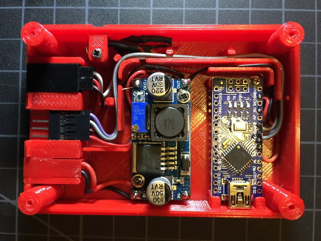
This text appears to be a DIY guide for building an Arduino-based transmission shift indicator system for a vehicle with a 700r4 or TH350 transmission. The system uses a linear potentiometer and buck converter to provide a 5V output to the Arduino, which then controls an LED backpack display to show the current gear position. Here are some key points from the text: 1. Building the system involves soldering leads onto the buck converter, wiring up the Arduino, and assembling a control box enclosure. 2. The linear potentiometer mount is attached to the shift linkage using a pushrod system. 3. The system uses color-coded jumper wires to connect components within the control box. 4. A small "button retainer" clip is used to secure the tactile switch in place. 5. The system can be powered from an ignition (on) 12V source, and a fuse tap is recommended for safety. 6. The programming instructions involve holding the calibration button until the display flashes on, then shifting through each gear position to store their locations. 7. The Arduino sketch uses EEPROM memory to store the gear positions long-term. The text also includes some build notes and suggestions for modifications, such as using screw-in brackets instead of velcro for mounting the control box, and printing out a schematic and programming instructions for future reference. Overall, this guide appears to be a comprehensive DIY project that requires some technical expertise and attention to detail.
With this file you will be able to print GM 700r4 Arduino based Programmable Shift Indicator with your 3D printer. Click on the button and save the file on your computer to work, edit or customize your design. You can also find more 3D designs for printers on GM 700r4 Arduino based Programmable Shift Indicator.