Goibniu (pronounced Gov-new) 3D Printer
thingiverse
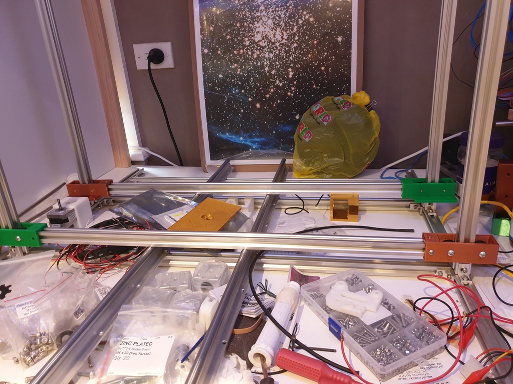
I'm currently designing/building a new 3D printer. My first one was built via a design on here (https://www.thingiverse.com/thing:1429273) and I've learnt a lot since then... so now I'm trying to design my own from scratch (more or less). I'm using 2020 aluminium extrusions with a footprint of 800X700mm, I considered making a larger Y axis but I didn't want my build space to stretch out a meter or so from the wall and the cost for linear rails beyond the 800mm I have tends to jump quite dramatically. This is the first part I have designed for the printer, it's intended to be the X axis gantry... it's comprised of linear bearing portions (will need to print one for each side). The main platform, which currently has space for two extruders using https://www.thingiverse.com/thing:71554 though I have not tried it yet). And one cold end lock for under the gantry... this should bolt into the underside matching portion and be secured by a nut (I considered designing a space to slot a nut into it, but after issues with my previous extruder cold end access... I just wanted something that would minimise fuss). The idea here is that the gantry is modular... you can either just use one extruder or run two per platform (with the option to theoretically run more platforms if you have the space). I hope to update as I continue with this build. Edit: 13/12/2019 Last weekend I printed the parts I had posted up here and noticed a few issues, the first being that I had neglected to make sure the space between the bearing mounts was sufficient to sit between the 2020 extrusion... that should now be fixed. I also realised I hadn't designed a way to attach the X axis belt to the gantry/platform... this has been removed until I can figure that out. I have uploaded Z axis mounts and threaded rod guide holders along with motor mounts... this should more or less sort out the Z axis. The gantry for the Z axis has a potentially temporary setting for the X axis motor... but I haven't tried it yet and I'm not sure of spacing... I've really only provided some mounting holes for a future mounting bracket. I'm hoping to go to my hackerspace tomorrow to print some of these parts, then I should be able to gauge if they will be functional yet or need further revisions. Update 15/12/2019 Ok, so I got in to my hackerspace yesterday and printed a couple of parts on the Prusa's... what I didn't realise is I hadn't set the supports properly in Prusa Slicer so the prints more or less failed. Having said that... I did learn enough to know I needed to make some alterations. The Z axis mounts (both with threaded rod insert and motor mount) have been edited as one of the mounting bolt holes hadn't gone through enough... I also noticed that I hadn't allowed a way for the motor's shaft to fit into the piece... so that was fixed. Oh... and I now have a name. I've been trying to think of a unique name, scouring Greek and Roman mythology for appropriate names. Then I decided to dip into my Irish ancestry and found Goibniu (pronounced Gov-new) who was "The most famous blacksmith in Irish mythology, he was one of the Tuatha de Danann, contemporary with Nuada Argetlam and the Dagda. So unless anything "better" comes along... this printer will be known as Goibniu. Update 6/1/2020 New year, new part... or something like that. 2020, the year of my 2020 printer... ok I'll stop now. So I was looking at the parts I had designed and made a quick mock up in Fusion of the frame and then overlayed the parts where they will sit on it and noticed a pretty big issue. My Z axis mounts didn't really allow for the 2020 extrusion holders... well they did, but where they sat would have meant the inner width of the X axis was quite a bit smaller. So I've redesigned the Z axis mounts to basically slot over the Z axis, then you run a delrin bearing (I think that's what it's called) into position, thread a M5 rod through and bolt it on the opposite side, do the same for the other side of the 2020 and you should have one side taken care of... repeat this for all four Z axis pieces of extrusion and you should have a nice running mount on which to fasten your Z axis plate (the one that will need a bit more work done but that will eventually hold the nut which should help keep the Z axis steady.) and the 2020 extrusions that will form the X Axis. My local hackerspace is open again this weekend I believe so I will try and get in and print some more parts to see how it's all going. Update 6/1/2020 (about 4:15pm not like the last one which was around 3.15am or so) So there's a bit of a theme here... after going to bed after designing the Z Axis mounts last night... it occurred to me that I hadn't checked to make sure the placement was right for the delrin wheels to sit in the extrusion. Sure enough, when I got up and checked, they weren't even touching. So a bit of fiddling and some help (thanks Michael Tippett) I had them repositioned and they look like they should be in the right spots now to have the wheels sitting nicely in the channels. I'll try and get at least one printed this weekend to see if that's correct or not. Fingers crossed. Update 22/02/2020 I didn't make it into my Hackerspace today due to family wellness concerns, but I did spend time yesterday designing some of the parts I was going to print... as such these are untested. I redesigned the Z-axis gantry, one with a mount for the X-axis motor and the other with a mount for the X-axis tensioner (this one bolts straight through to the Z-axis bearing mounts). The tensioner I designed is a variation of others I've seen on here, but rather than have a printed threaded portion, I've designed it to fit a M5 bolt, the head of which should slot into the back of the bearing holder and the rod should slot through the tensioner. The intent is to then design a part that will sit over and hold one or two nuts, this part should be able to be "dialed" which will pull the bearing holder closer or push it further away from the tensioner thus pulling the X-axis belt tighter or giving it slack... theoretically. I also cleaned out the files that were here as I've lost track of which ones I've printed (and either work or I've found don't work)... they have been updated with the latest version of files. The Z axis bearing mounts have two versions because though I designed one with tighter tolerances for the bearings (Z Axis Gantry Left/Right V5) I think I ended up actually printing the (Z Axis Mount Left/Right... for some reason I changed the name too)V4 version for my setup... this was by accident, but I figure I'll run with it and see if a little bit of extra play is an issue or not. Update 29/2/2020 I got some time at the Hackerspace to print some more parts today. It wasn't until I got home and checked dimensions that I discovered the hole for the lead screw nut is just a smidge too small... I'm fairly sure I had the correct measurement in Fusion360 (and this is basically the same as the larger part of the lead screw which I had an issue with in a previous version)... so it may just be that to allow for printer variance in dimensional accuracy I needed to allow an extra .5mm or so (which is what I did for the larger part). I'm debating if I end up just filing the hole until I can slot it in... but it's up to you if using this design if you want to see if your printer is dialed in enough to get it right or if it needs a little adjusting. I'm still not entirely sure about my tensioner design... the main thing I think I might need to do is change how much space is available for adjustment as at the moment there's not much... having said that I'm not really sure how much would be needed to get a good tightness for the X axis belt. 27/7/2020 Just wanted to say I am still working on this... I do tend to work at less than a snails pace though. My current printer (a Sunhokey Prusa i3 Clone I believe... it was given to me by a fellow hackerspace user, Thanks!) is being very temperamental so I'm kind of trying to get that working well enough to print the parts for Goibniu (it has extrusion issues and I'm in the process of trying to upgrade it to a direct drive to try and help with that). I've currently got the X axis gantry raised but one of the bearing mounts for the platform broke so I have to reprint that (the previous print had horrible underextrusion). It's looking ok but there is a bit of slop in the Z axis mounts... this might require a rework of parts in the future but I won't know until I can start tuning it. Update 5/12/2020 I just wanted to post a quick update, partly to show I am still about and also to let anyone who is interested know that I am actually getting closer to testing stage. I was printing some iterations of an extruder when my current printer's PTFE tube connector decided to pack it in... so I'm currently waiting on a replacement so I can continue with that. I've bought myself a big sheet of MDF as a build surface mounting point (I won't be using a heated bed so MDF should be fine). I'm having some trouble getting the rail system working smoothly. Part of that is due to issues getting my drill to go straight (I don't have a drill press)... I think I might be able to get around this (once I have my connector part) by making a designing/printing a drill hole guide. I'm also considering making an option to print a delrin wheel mount for the linear rail as I'm starting to think that might be a bit easier (the SBR12UU slide linear block bearings I have I think got a bit banged up in transit, so while they do run along the rail.... they don't seem as smooth as I'd like). If I can get my current printer up and running well enough I think I will design that option. My plan (in case I haven't mentioned it earlier here... it's late and I don't want to re-read, sorry), is to make the X axis platform capable of holding at least two extruders if someone wanted to run it that way. I'm not sure how easy that will be to implement but assuming Marlin or whatever firmware you run has an option to specify how far apart the extruders are, it should be fine. I'm also currently awaiting two different probes, one I believe is inductive and the other is a BL Touch clone. I haven't designed a mount yet (partly because I don't have dimensions required, partly because I only just remembered I don't have any endstop option planned), but will do once I have at least one of those in hand... I will try and make it a changeable mount, so if you have one sort of sensor but then change it... you can just print a new mount and swap them over too. I work slowly (motivation comes and goes sporadically)... but I hope to have some more progress before the end of the year... if I was really optimistic I'd say I'd hope to have a test print before the year is out... but we will see how that goes, I wouldn't bet on it ;). Have a safe and happy festive season and let's hope 2021 is far better for the world in general! Also, sorry for the lighting in my photos... and the mess... but that's just how I work. Any donations (of any value) are much appreciated and will help motivate me to take this design further! Update 18/12/2020 After multiple attempts at drilling the holes for mounting the bearing blocks it occurred to me that I could design a little guide for the drilling. Hence the latest edition to the file list is a drilling guide for a SBR12UU bearing block. I found that my drill would slip and so the alignment wouldn't be perfectly squared... now I should be able to print this guide, clamp it to my build surface and drill with accuracy. It is currently untested as my printer push fit connector died recently and I'm waiting on a replacement part before I try printing.
With this file you will be able to print Goibniu (pronounced Gov-new) 3D Printer with your 3D printer. Click on the button and save the file on your computer to work, edit or customize your design. You can also find more 3D designs for printers on Goibniu (pronounced Gov-new) 3D Printer.