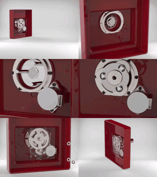
Grundfos : Gearbox for Hydronic Valve (A Practical Setup)
grabcad
The design allows easy assembly and reassembly in the Z direction. To maintain concentricity and alignment even after multiple setups, the enclosure box is provided with extrusions that guide components to their respective places with only minor adjustments.Stepped Planetary gear was selected as it provided more reduction per width of the gearbox compared to two steps planetary transmission. In addition, the ring gear fasteners could share the radial stress of 300 N in the shaft, endured alone by the bearing otherwise. Also because it is more efficient, precise and compact, compared to simple spur gear reduction.Gear ratio is 597:1, considering 5% loss at each spur gear mate and an overall 5% loss in the planetary set.The foremost mindset kept in the design was to reduce possible vibrations in the shafts and gears. To achieve this, the strategies taken were to bring the gearbox as close to the base as possible (In our case, the gearbox was limited to 35mm out of the allowed 50 mm from the base), provide sufficient bearing support to the shafts and eliminate keys by including gears embedded on shafts.The design assumes that the enclosure box is not strong enough to hold the components using the threads. Threaded inserts have been included in the design to hold the components. According to the production quantity and the equipment available, these can be added either before molding (Insert Molding) or after using heated shafts.
With this file you will be able to print Grundfos : Gearbox for Hydronic Valve (A Practical Setup) with your 3D printer. Click on the button and save the file on your computer to work, edit or customize your design. You can also find more 3D designs for printers on Grundfos : Gearbox for Hydronic Valve (A Practical Setup).
