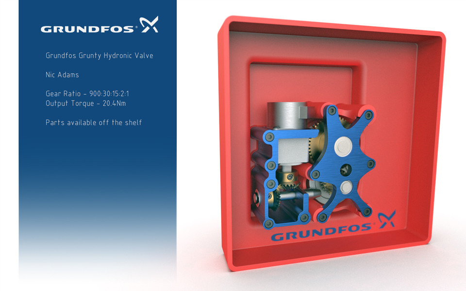
Grundfos Grunty Hydronic Valve
grabcad
Final assembly attached.Total reduction ratio of 900:1, (900:30:15:2:1).Stage 1: 30:1, Size 8, CSF-1U-CC, HarmonicDrive reducer, 70% nominal efficiency.Stage 2: 1:1, 25 Tooth, KHK spiral miter gear transfer, 97% nominal efficiency.Stage 3: 45:3 KHK hypoid gear set, 86% nominal efficiencyStage 4: 24:48 KHK ground helical spur coupled to output shaft, 97% nominal efficiency.Output torque approximately = 0.040Nm (@900rpm) x 900 x 0.58(Total efficiency) = 20.4Nm The gear box can be customised in several ways including at the HarmonicDrive where the unit is available in 30, 50 and 100 ratios. The output spurs can also be varied from 1:1 through to 2:1. This would allow for a range between 450-1500:1. As described below, a motor of higher torque can be accommodated in the same space.All transfer components are available off the shelf and specified to the correct tolerance and torque capability. Bearings supplied by AST and SKF. BOM references attached.Should the HarmonicDrive unit prove costly, a generic of the same type is available through 3F Famed.I've also included mount holes for an uprated equivalent stepper motor. The quoted stepper assumed to be a TSM35-5V type can be replaced with a TSM42-5V providing upto 50% more torque. The alternative still fits within the build envelope.Some secondary machining of standard items would be required. The hypoid pinion is supplied with ample stock for axle machining. The initial primary bevel gear has a bore of 8mm while the HarmonicDrive unit has a D axle of 9mm, manufacturer should be able to customise the ouput shaft to suit.Bearings have been chosen to accommodate radial and axial thrust loads.Some additional hardware, such as shims and washers have not been included for lack of time and appropraite tolerancing. Also, shaft keys would need to be added for output shafts.Although stress analysis is not yet provided, the top plate of the last two output stages, in conjunction with the enclosure body standoffs and mounting hardware, will support the prerequisite loads.I've included some draft in the mounting standoffs for molding purposes.Additional mounts for the rest of the stages can be produced in appropriate plastic or extruded alumium for best tolerance.Ball bearings at all load points ensure long life.Added an exploded animation and BOM.Thank you to Grundfos for posing the challenge, it certainly had my brain churning,Update: Added an alternate first stage bracket which may simplify manufacturing.
With this file you will be able to print Grundfos Grunty Hydronic Valve with your 3D printer. Click on the button and save the file on your computer to work, edit or customize your design. You can also find more 3D designs for printers on Grundfos Grunty Hydronic Valve.