H-Pattern Shifter
prusaprinters
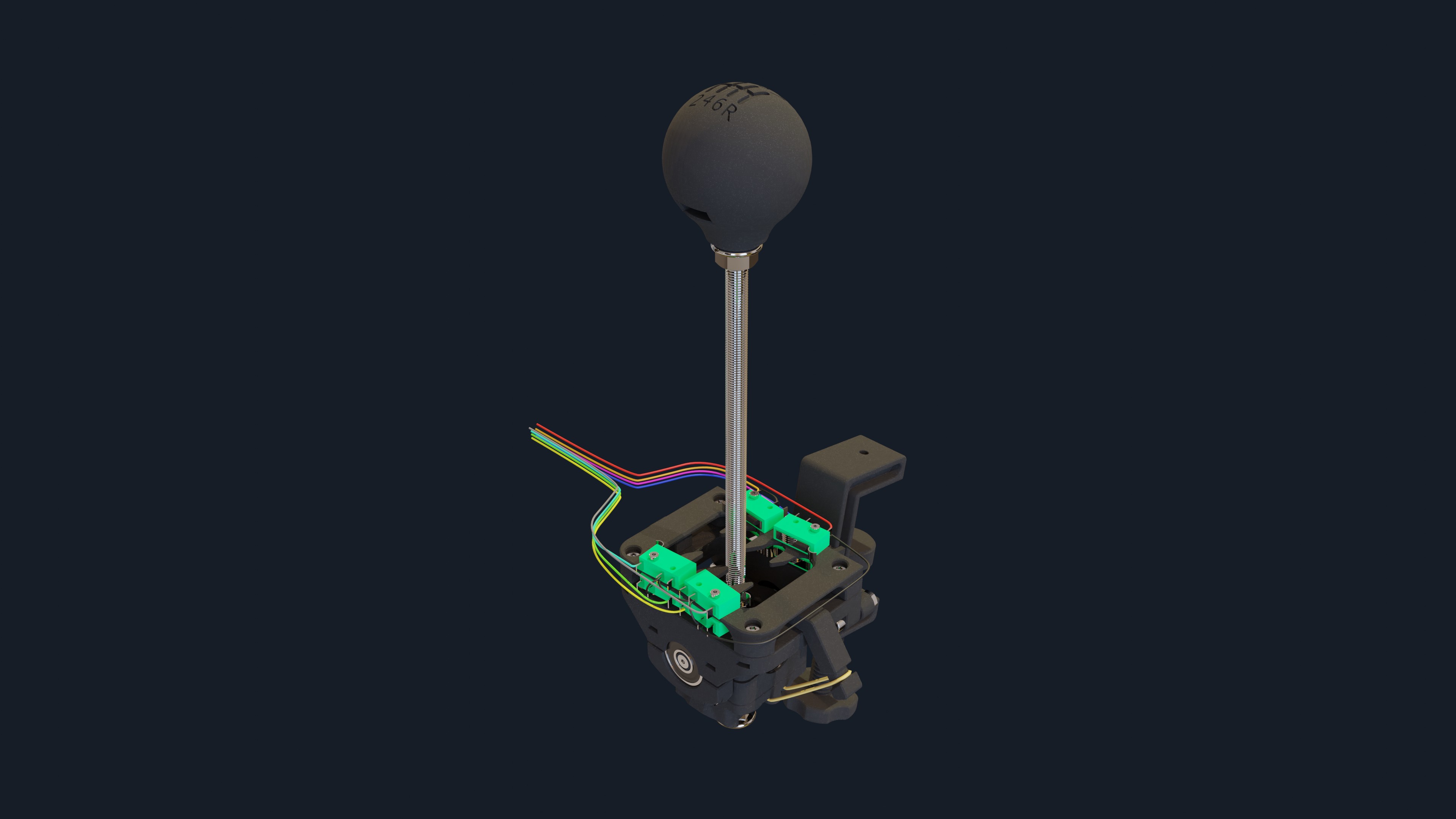
<h3>H-Pattern shifter assembly manual</h3><p>This is the assembly manual of a fully functional H-Pattern shifter for PC. </p><h4><strong>Needed parts </strong></h4><ul><li>All the printed parts (the amounts can be found in the description of every model)</li><li>Parts you need to buy:<ul><li>1 x Raspberry Pi Pico (<a href="https://www.raspberrypi.com/products/raspberry-pi-pico/">Raspberry Pi Pico – Raspberry Pi</a>)</li><li>8 x Microswitches; I bought microswitches from the local store, but they are the same as microswitches on <a href="https://www.aliexpress.com/item/1911059086.html?spm=a2g0o.productlist.0.0.3568a51aSTyk3s&algo_pvid=3dabc93e-4eb2-4a80-9efd-03bf1cce35db&algo_exp_id=3dabc93e-4eb2-4a80-9efd-03bf1cce35db-42&pdp_ext_f=%7B%22sku_id%22%3A%2266506581058%22%7D&pdp_npi=2%40dis%21HRK%2120.74%2114.54%21%21%21%21%21%40210318cf16608590094357378e24c9%2166506581058%21sea&curPageLogUid=TmRDzJENixzP">link with<strong> arc lever</strong></a> </li><li>5 x Roller bearing 608-2RS or any 608 bearing will do; I have bought one of the cheapest in local store and it is pretty smooth (<a href="https://www.skf.com/uk/search-results?q=608&searcher=all&site=315&language=en&tridion_target=live&tridion_version=3&language_preset=English">608 bearing</a>)</li><li>Screws / nuts:<ul><li>4 x DIN 912 M2x16 </li><li>2 x DIN 912 M3x8</li><li>12 x DIN 912 M3x12 </li><li>4 x DIN 912 M3x16 </li><li>2 x DIN 912 M4x16 </li><li>4 x DIN 912 M4x20 </li><li>4 x DIN 7991 M3x16 </li><li>22 x DIN 562 M3</li><li>1 x DIN 562 M8</li><li>4 x DIN 934 M2</li><li>4 x DIN 934 M4 </li><li>4 x DIN 6923 M8 </li><li>1 x DIN 976 M8 - Threaded rod which is defining the height of the shifter (min. 150mm); I have used 250 mm rod and it may be a little too long.</li></ul></li><li>Mounting clamp - Currently the only way of using this shifter is by clamping it onto the desk and for that purpose you need to make a Mounting clamp (<a href="https://www.printables.com/model/230759-mounting-clamp">Mounting clamp by Kyboky | Download free STL model | Printables.com</a>). All needed parts and assembly instructions can be found on the link above. </li><li>The wires for connecting microswitches to Raspberry Pi Pico; I have used 9 different colors so that every microswitch has its own color and one common color (black) that is connected to ground.</li><li>Tools:<ul><li>Allen wrench (1.5, 2, 2.5, 3) - for tightening all the screws</li><li>Wrench (7, 13) - to help hold nut while tightening screws and tightening nuts.</li><li>Soldering iron and all the equipment needed for soldering.</li><li>Pliers for cutting the wires and removing insulation.</li></ul></li></ul></li></ul><h4><strong>Printed Parts</strong></h4><p>All of the parts for my prototype were printed in PLA with layer height of 0.2mm. All the parts were printed without supports with the one exception - <i>Vertical_Movement_Stopper.</i></p><p>The reason for printing in PLA was simple, that was the only material I had at the moment, PETG or any other material would be as good, probably even better.</p><h4><strong>Assembly</strong></h4><p>There is an interactive guide of the assembly process <a href="https://kyboky.github.io/H-Shifter_Web_View/">here</a>.</p><h4><strong>Electronics</strong></h4><p>Raspberry Pi Pico is used as the “brain” of this shifter for a simple reason - it is cheap, can be recognised by PC as USB HID and is locally available. </p><p>Currently in this version there is no place to mount Raspberry Pi Pico.</p><figure class="image image_resized" style="width:62.8%;"><img src="https://media.printables.com/media/prints/261473/rich_content/39cc1840-2a93-45fd-a468-1dc212344ed8/image.png#%7B%22uuid%22%3A%223625d2f8-f115-4333-8232-af62d5c96e96%22%2C%22w%22%3A633%2C%22h%22%3A514%7D"></figure><p> <i>Raspberry Pi Pico pinout (</i><a href="https://datasheets.raspberrypi.com/pico/Pico-R3-A4-Pinout.pdf"><i>Pico-R3-A4-Pinout.pdf (raspberrypi.com)</i></a><i>)</i></p><p>For purpose of the shifter pins 4-12 have been used as they were all the pins needed in one place. One GND and 8 GPIOs for 7 gears and reverse.</p><p>As we need to connect microswitches to Pico there is a little bit of soldering. One of the terminals, in this case NO, has to be connected to GND (ground) on the Raspberry Pi Pico. The other terminal of the microswitches, in this case C/COM, has to be connected to the GPIO (general-purpose input/output) on Raspberry Pi Pico (GPIO2-GPIO9 in my case). The GND can be interconnected between microswitches but every microswitch needs a wire for GPIO.</p><p><strong>WARNING: Soldering can be dangerous if safe operating procedures are not followed.</strong></p><h4><strong>Programming</strong></h4><p>First you have to flash CircuitPython on Raspberry Pi Pico (<a href="https://learn.adafruit.com/getting-started-with-raspberry-pi-pico-circuitpython/circuitpython">Installing CircuitPython</a>).</p><p>After flashing CircuitPython onto the Raspberry Pi Pico extract <i>RPiPico_Code.zip</i> and place all the files on the Raspberry Pi Pico.</p><figure class="image image-style-align-center image_resized" style="width:80.03%;"><img src="https://media.printables.com/media/prints/261473/rich_content/910c95d5-0aaa-448d-a970-47658279fca3/image.png#%7B%22uuid%22%3A%223729715a-35ee-4277-89d2-437cfb077a4b%22%2C%22w%22%3A743%2C%22h%22%3A160%7D"></figure><p> <i>Files on Raspberry Pi Pico after flashing and copying files onto it</i></p><p>In the case of not using same GPIOs (GP2-GP9) there are some changes that have to be done in <i>code.py</i>.</p><pre><code class="language-python">firstGear = DigitalInOut(board.GP2) firstGear.switch_to_input(pull = Pull.UP)</code></pre><p>In <i>code.py</i> every gear is defined something like this and board.GP2 is defining which GPIO is used for a gear. Depending where you solder the wire from microswitch you have to change <strong>board.GP{number of GPIO}</strong>.</p><h4>Preflight check </h4><p>Go to <strong>Control Panel → Devices and Printers → Right click Pico → Game controller settings → CircuitPython HID Properties</strong></p><p>Here you can check if every gear works by shifting into gear and see if some of the buttons light up.</p><figure class="image image_resized" style="width:45.09%;"><img src="https://media.printables.com/media/prints/261473/rich_content/8bd12d1a-2e46-4774-ab24-ec223eab5334/image.png#%7B%22uuid%22%3A%22c6823512-9f27-4b78-8c75-4bddd00772d6%22%2C%22w%22%3A393%2C%22h%22%3A452%7D"></figure><p> Sample of shifting into 1st gear</p><p> </p><p>If you made it this far you will have a fully functional H-Pattern shifter for gaming.</p><p>Happy gaming!</p>
With this file you will be able to print H-Pattern Shifter with your 3D printer. Click on the button and save the file on your computer to work, edit or customize your design. You can also find more 3D designs for printers on H-Pattern Shifter.