Hadley 114/900 Telescope Remix
prusaprinters
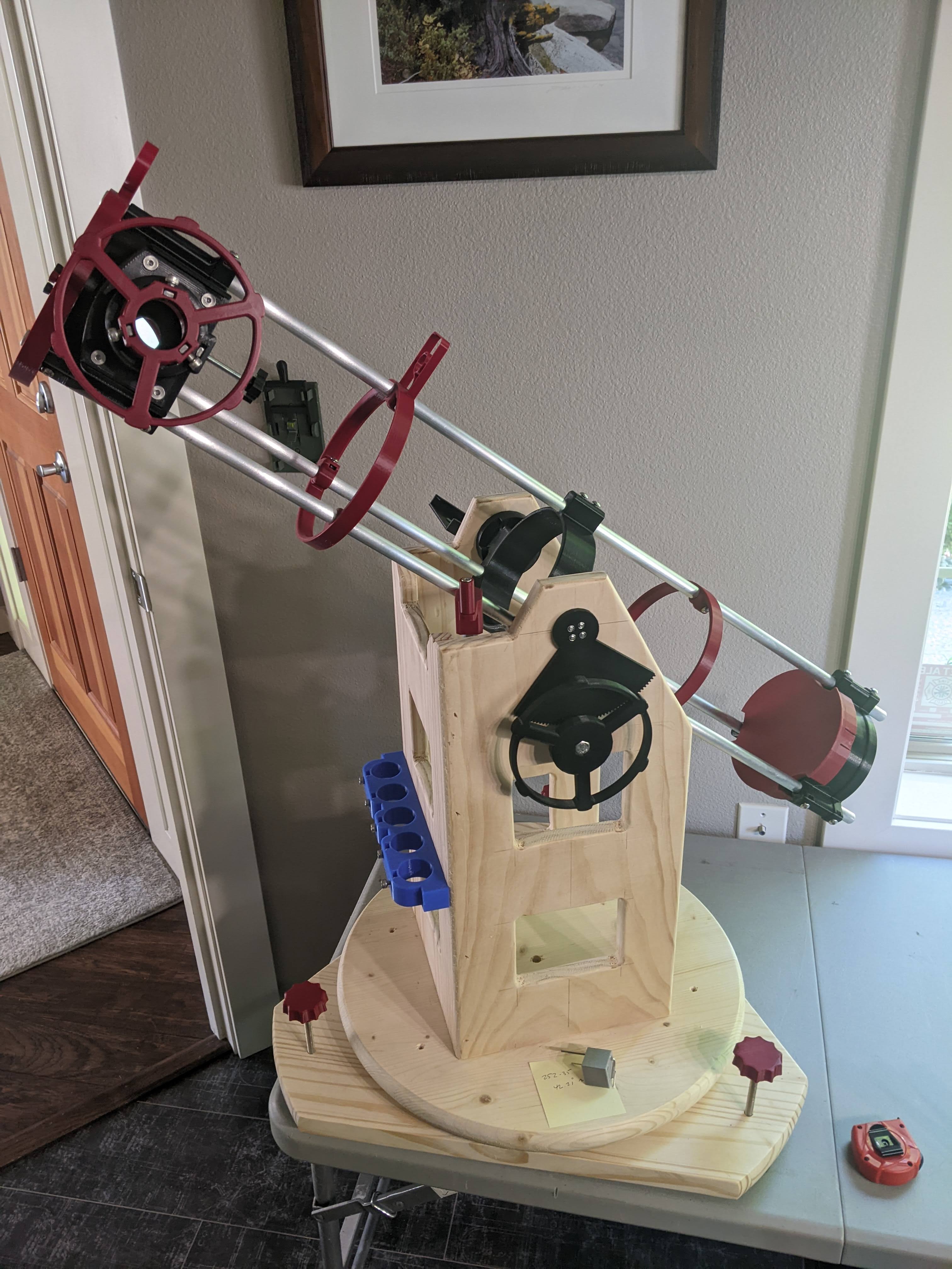
<p>My modest remix of Maff's excellent model.</p><p>Changelog to the original design:</p><ol><li>Optimized for 100% metric fasteners (ALL M5 unless noted otherwise)</li><li>Tweaks to the bolt orientations/approach for both mirror holders</li><li>Removed all of the lettering (personal preference item)</li><li>Included a couple dovetail versions of the mount interface to suit my mount</li><li>Mixed some options for the sights</li><li>8.6.22 changed BOLTS to NUTS in the spider explanation (dumb dumb)</li><li>8.6.22 added BOM by request</li></ol><p><i><strong>“SPIDER HUBBLE CRITICAL NUT SPACING": </strong></i></p><p>I've included both STL and 3MF files for just about every piece. If any piece doesn't have a 3MF it was just too simple to worry about. Please feel free to work with the STL's as you see fit BUT, I would HIGHLY recommend that you stick to the 3MF for the “Spider Hubble” part because (as indicated) the spacing of the internal NUTS inserted during the print are <strong>super critical</strong>. They are a double stack of NUTS that need to line up perfectly on the vertical axis or the lands won't hit correctly, and the bolts will cross-thread. I spent A LOT of time getting those perfect, so trust me on that one. </p><p>The NUTS that go in the 3 perimeter adjusting bolt locations of the “Spider Hubble” are as follows: </p><ol><li>Lower-level NUTS (first in the print) are a standard 5mm bolt that is 3mm thick. </li><li>Upper-level NUTS are a 5mm Nyloc at 4.9mm thick, inserted top down (the narrow nyloc part facing downwards). </li><li>There are pause notes added to the 3MF file to this effect as well.</li></ol><p>When it's all said and done, the socket head secondary adjusting screws thread down from the top, into the Nyloc retaining nut, then into the standard “guide” nut and then out the bottom of the spider to make contact with the secondary bearing plate (see pics). See the next section for more on that.</p><p><i><strong>SECONDARY HOLDER:</strong></i></p><p>The secondary mirror holder has been tweaked so that it will spin freely (when the 3 color-coded adjusting bolts are loose that is). To achieve that, I adjusted the hexagonal shaped hole in the base so that a 5mm Nyloc nut and washer will fit in there not grab the sides. This way, you can infinitely micro-adjust the secondary both up-down (using the center socket head bolt) and rotationally (by simply twisting the base) independent of one another.</p><p>The bolts used for the Spider-Secondary adjustment assembly are a 5mm x 50mm allen socket head. I used model paint to create the red and blue heads to help me keep things tidy during the collimation process.</p><p>To keep the adjustment bolts from digging into the plastic on the back of the Secondary Holder (doing damage and also letting the collimation get out of whack), I opted to insert a metal bearing plate (fancy name for a big 1" fender washer). I also created landing divots in the plate for the 3 adjustment screws so that they won't want to walk around when you turn them. By drilling about ⅓ of the way through the washer, you get a really nice retaining divot and also a tiny little dimple on the other side from the tip of the drill bit just before it breaks through. I mention this because the backside dimple serves a purpose as well…it holds the Secondary Base from rotating once the adjustment bolts are snugged up.</p><p>The spring here is the same as the three on the Primary Mirror (more later).</p><p>The center bolt between the Spider Hubble and the Secondary Holder is the same as above 5mm x 50mm allen hex head. The nut at the Spider Hubble is a Nyloc inserted face down. As mentioned above, the nut inside the Secondary Holder is also a Nyloc, standard configuration on top of a 5mm washer.</p><p><i><strong>PRIMARY MIRROR CELL:</strong></i></p><p>Instead of having nuts under the primary, I remixed the Primary Mirror Cell to snugly accept three 5mm hex head bolts, inserted <i>through the cell</i> and sticking out the back. (This way there is never any concern about possibly backing out the adjusting bolts from the nuts under the glued in place primary mirror.) </p><p>I once again color-coded the three printed thumb nuts with identifiable filament colors and mixed them to SNUGLY accept 5mm Nyloc nuts, so your mirror adjustments stay nice and solid.</p><p>The bolts here are M5 x 50mm standard hex head. You could get away with 40mm length here if you are in a pinch as they protrude right about 10mm through the thumb nuts.</p><p><i><strong>Springs:</strong></i></p><p>There are four springs in this design, 3 at the Primary Cell and 1 at the Secondary Holder. The best choice here (in my opinion) is a rectangular cut spring that sits perfectly flat on the plastic bearing surfaces. The springs I used are actually for 3D printer beds and come in a variety of sizes and strengths. The ones I used are linked here ($8.59 for 10 of them).</p><p><a href="https://smile.amazon.com/dp/B07Z4JXMM2?psc=1&ref=ppx_yo2ov_dt_b_product_details">MroMax 3D Printer Die Spring 10mm OD 20mm Long Spiral Stamping Light Load Compression Mould Die Spring Yellow 10PCS 3D Printer Spring Bottom Connect Leveling Compatible with 3D Printer Bed: AmazonSmile: Industrial & Scientific</a></p><p><i><strong>FOCUSER:</strong></i></p><p>I did not change much here, other than optimizing for metric fasteners. However, I do have a couple of observations/suggestions.</p><ol><li>The threads will require a little post-print attention to get them working smoothly. Do it.</li><li>Once I felt good about their general operational level, I added 2 or 3 layers of teflon tape to the threads. This serves two purposes: first, it makes them operate a lot smoother and second it tightens up the tolerances. by adding another and another layer of teflon tape you can effectively adjust the threads to be as loose or tight as you want them without messing with the model. I prefer not to screw with threads, pun intended.</li><li>The hardware for the brake is a M5 square nut and a M5x45 hex head bolt with a printed thumb screw. The long bolt here, while not super good looking, is much more finger friendly because it gets the bolt outside of the adjusting wheel.</li><li>The hardware that holds the eyepiece in place is three M5 square nuts and three M5x12 hex head cap screws (easier to turn with your fingers)</li></ol><p><i><strong>SIGHTS:</strong></i></p><p>There are a couple options here I messed around with.</p><ol><li>“Sights” is the original design, optimized for metric hardware. These can go anywhere you want on the support rods and will spin on the rods so they allow/require alignment.</li><li>Rear/Front Sights “on Support Rings”. Here I stole another of Maff's models and remixed it to be a simple naked 3-rod ring, but with the sights tagged on. I find these to be kind of cool because; A. they provide extra rigidity to the overall assembly (that it in no way needs) and B. they automatically align the sights with the rods/assembly. Granted, you no longer have the ability to rotate the sights on the rods, but the manual sights are very rudimentary, so I really don't see them improving appreciably beyond being simply welded to the main optical axis of the rods. YMMV</li><li>Hardware - see below</li></ol><p><i><strong>Typical Hardware (not mentioned in sections above):</strong></i></p><p>There is a lot of leeway here to use what you want or what is available easily to you, but I will list out exactly what I used (and why in some cases). If the length of something is critical, I will say so, otherwise you could go longer if you don't mind having extra bolt sticking out all over the place.</p><p><i>A note on nuts</i>: In most cases around the perimeter assembly, you'll see that I used square nuts. They are a little harder to find sometimes and you can certainly get away with standard hex nuts if you prefer. I prefer the square nuts for the extra amount of side contact they provide in a "captured nut" configuration where you're counting on plastic to keep them from spinning out. YMMV again</p><p><i>Another note on nuts</i>: most of them are going to slip right into the capture slots perfectly, just slightly snug. Some are going to be a little looser and may even slide back out if titled. A few are going to require a tiny bit of filing inside the slot. This is due where each slot lands in the actual layer counts moving up the model, and how that relates to what the chosen layer size is for each print. It all works as-is with a minimum of effort, but if you want to head in and count layers/adjust nut locations to make it PERFECT in all cases, please be my guest. Not it!</p><p><strong>Lower Tube Assembly</strong> <strong>to rods </strong>- Six M5 square nuts and six M5x12 button head bolts</p><p><strong>Mount Interface Dovetail</strong> <strong>to rods </strong>- Six M5 square nuts and six M5x12 button head bolts</p><p><strong>Upper Tube Assembly to the rods</strong> - Three M5 square nuts and three M5x12 button head bolts</p><p><strong>Upper Tube Assembly to the Spider Hubble</strong> - Three M5 square nuts and three M5x8 button head bolts</p><p><strong>Sights (all options)</strong> - These are all M4 nuts and M4x12 button head screws. I wouldn't go any longer here, at least on the Support Ring options because the bolts will be tough to get a tool on and will eventually foul on the Support Ring if you go too long.</p><p><i><strong>THOUGHTS ON COLLIMATION, MIRROR DOTTING, ETC.:</strong></i></p><ol><li>The following assumes you, like me, know nothing about setting up a telescope</li><li>The process of Collimation will freak you out at first, but don't sweat it, it's not that big a deal</li><li>All the collimation helper videos and whatnot will indicate a center dot on the Primary Mirror. When you get your mirrors the primary likely won't have a center dot, also not a big deal. I've included an excellent link below that walks you through it…easy.</li><li>(Hint: the center of the primary mirror doesn't get used anyway, so ya…dot away)</li><li>Regarding placement of the UTA and LTA on the rods…isn't this dimension super critical?? Well, yes and no. It's important that you stay within the limits of the focuser, but it's not a micro-millimeter problem. I've included a link below to Newt for the Web which is a full-throated telescope designing tool provided by the good folks at Stellafane. In this case, instead of plunking in hypothetical numbers for some future brain-child scope you're thinking about, you can stick in the ACTUAL numbers for your printed out scope and get ACTUAL geometry.</li><li>Newt takes some time to get used to, but it's worth it. I also HIGHLY recommend looking around the other bits of Stellafane because there is a TON of good info on there regarding scope design that will vastly improve your personal knowledge on the subject.</li><li>Spoiler alert: If you leave the basic geometry of the original model alone (I did), use the eyepieces suggested by Maff (I did that too) and want a little extra "in-focus" (I did, 13mm to be exact) your overall length measured from the base edge of the LTA to the top edge of the UTA will come to 861.5MM (lol at point 5).</li><li>I really don't know if that number puts me at the extreme ends of anything or not, but it works, focuses on infinity perfectly with some room to spare in each focuser direction (so you can use it as a terrestrial scope and whatnot) and nthing falls out of the ground.</li></ol><p>Well, I think that's it but if I missed anything please let me know and I will amend. I will also be posting a separate design of the mount (and all its pieces) in a little while, so watch for that. Everything in the photos not directly attached to the scope will be in the mount posting.</p><p> </p><p>Mentioned Links:</p><p><a href="https://www.youtube.com/watch?v=4gpMuQrgyJo">How To Centre Spot A Telescope Mirror - YouTube</a></p><p><a href="https://stellafane.org/tm/newt-web/newt-web.html">https://stellafane.org/tm/newt-web/newt-web.html</a></p><p>Links to other helpful spots I've found on this journey:</p><p><a href="https://skyandtelescope.org/astronomy-resources/how-to-align-your-newtonian-reflector-telescope/">How to Align Your Newtonian Reflector Telescope | Sky & Telescope - Sky & Telescope (skyandtelescope.org)</a></p><p><a href="https://www.bbastrodesigns.com/NewtDesigner.html">Newtonian Reflecting Telescope Designer (bbastrodesigns.com)</a></p><p><a href="https://www.kirchdorferweb.com/astronomy/focuserform.html">https://www.kirchdorferweb.com/astronomy/focuserform.html</a></p><p><a href="https://www.astro-baby.com/astrobaby/help/collimation-guide-newtonian-reflector/">Collimation - Newtonian Telescope - Reflector - Astro Baby's Guide to (astro-baby.com)</a></p><p><a href="https://stellafane.org/">Stellafane: Home of the Springfield Telescope Makers</a></p><p>EDIT: The rods remain unchanged at ½" diameter and 36" long. I had these cut for me to length from solid aluminum by onlinemetals.com. Total cost delivered to my doorstep was 32 bucks. You could use hollow rods or steel or whatever you choose. The holes in the model are 13.4mm so if you're going with metric rods you MIGHT be able to use 13mm but you also might end up needing to do a little reaming if your printer squishes those holes too much. 12mm would work for sure and the set screws will hold everything nice and tight.</p><p> </p>
With this file you will be able to print Hadley 114/900 Telescope Remix with your 3D printer. Click on the button and save the file on your computer to work, edit or customize your design. You can also find more 3D designs for printers on Hadley 114/900 Telescope Remix.