Hall-Theta (Hall-O) Z-Probe Bed Leveling Mount for Rostock MAX
thingiverse
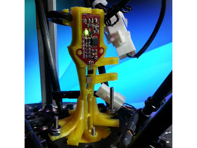
Work in progress - follow for updates. Update - 3-6-15 The previous "mount mounter" has been replaced with upper and lower mounters. This provides two benefits. First, the lower mount has projecting "feet" that will absorb the impact should there be a bed crash. This will prevent the probe's mounts from being sheared off in the event your firmware fails to respond to a probe hit, either because of loose wiring or a firmware crash. Second, the new mounts stiffen up the probe immensely. I found that the probe's wiring could pull at the top of the probe a little bit as the platform moves around, and the new mounts constrain things enough to counter this effect. I got a slightly better (less error, more repeatability) as a result. Note: The probe itself hasn't changed since the 1-31-15 update, but if your probe was printed from a version older than that one, you'll need to download and print a new one. (Old changelogs at bottom) Who is this for, and what do I need? The Rostock MAX is a great printer, but it really needs help printing in some places at the edge of the build surface. Due to the vagaries of delta printer kinematics, whenever the carriage must travel "outside the triangle" formed by the three towers, positioning errors become highly likely. If all you ever print is little stuff that fits inside the triangle, you probably don't need this. However, if you DO print things that go outside of the triangle, this may be the only way to get decent prints. If you want to use this probe, you probably need to get a controller board that runs Smoothieware, such as the Smoothieboard or Azteeg X5. We have a user with two different boards (an X5 and a Smoothieboard) who has used this probe to calibrate a Rostock MAX and another delta printer, and it worked fine. Why not just use the auto-calibrate from Repetier or Marlin? We tried - the results were worse than manual calibration, and were useless for printing. That might change by the time you read this, so you might want to check on it before investing in a new board. However, the ARM-based processors you get with a Smoothie controller are exponentially more capable than the Arduino-based controller your printer probably has now, and the Azteeg X5 is quite affordable compared to an older board like the RAMBo, so it's not a bad buy. (Personally, I recommend the Smoothieboard 5X, which has big beefy power FETs - my Azteeg X5 lost its heater FET last year after only a couple months.) Whatever board you get needs to have either two Z endstop connectors (min and max) or a Z probe connector (basically the same thing, just marked differently.) Probe Repeatability This was tested using G29 on my Smoothie fork: [PR] Repeatability test: 10 samples (S) [PR] Acceleration (A): 90.0 [PR] Debounce count (B): 0 [PR] Smooth decel (D0|D1): true [PR] Eccentricity test (E): on [PR] Probe smoothing (P): 1 [PR] Probe priming (Q): 5 [PR] Feedrates: Fast (U) = 70.000, Slow (V) = [PR] 1 step = 0.00938 mm. [PR] Priming probe 5 times. [PR] Test 1 of 10: Measured 1136 steps (10.650 mm) [PR] Test 2 of 10: Measured 1136 steps (10.650 mm) [PR] Test 3 of 10: Measured 1137 steps (10.659 mm) [PR] Test 4 of 10: Measured 1136 steps (10.650 mm) [PR] Test 5 of 10: Measured 1136 steps (10.650 mm) [PR] Test 6 of 10: Measured 1136 steps (10.650 mm) [PR] Test 7 of 10: Measured 1136 steps (10.650 mm) [PR] Test 8 of 10: Measured 1135 steps (10.641 mm) [PR] Test 9 of 10: Measured 1136 steps (10.650 mm) [PR] Test 10 of 10: Measured 1136 steps (10.650 mm) [PR] Stats: [PR] range: 2 steps (0.0188 mm) [PR] mu: 1136.000 steps (10.650 mm) [PR] sigma: 0.447 steps (0.004 mm) [PR] Repeatability: 0.0188 (add a little to be sure) Most G29s I run return anywhere from 0 to 0.02mm (20 microns) of repeatability. For reference, we want 30 microns or better to calibrate for an acceptable 1st layer at a height of 0.1mm, so 18.8 microns is fine. Origin of the idea This is a reinterpretation of Marco Antonini's Rostock Z-Probe, done in Sketchup. His probe doesn't fit to a Rostock MAX platform, so I decided to design a new mount that would, as well as accepting neodymium magnets you can get from Amazon and a metal rod you can get from McMaster-Carr (both of which are ideal if you're in North America.) I also thought the original probe didn't look threatening enough, so I embellished that a little. At the moment, this part (and the instructions) should get you up and running with a basic Z-probe. . OLD CHANGELOGS: Update - 1-31-15 A "mount mounter" has been added. This is a yoke that you can bolt to your effector, and the main mount can be snapped in place and fastened with a screw (although it fits tightly enough for me that I haven't needed to bother). The main mount has been modified to fit properly with the yoke, so you'll need to download and print it again! The advantage of this is that you don't have to use probe offsets, because the probe will be perfectly centered. If you're using this to do an auto calibration, you really should avoid probe offsets because they suck and they are terrible and they stink and they will degrade the quality of your calibration. I know this from experience! Update - 10-22-14 Board holder has been resized a little to make fitting the board easier. Also, the side mount has been lengthened. If you mount the probe with the side mount, inside the effector, it should be right in the middle! This is the best possible place for a probe to be mounted. Update - 7-8-14 I added a platform mount to the side of the probe, about 2/3 of the way up. This allows the probe to work with an E3D mounted under the platform. I've also added a calibration piece, which contains only the probe rod passage holes. You may need to adjust your filament flow to get these just right: enough pressure to keep it steady, but not enough to stop it from moving freely. Instructions Prerequisites The first thing I have to tell you is that you should seriously consider ditching your Arduino-based controller (RAMBo, RUMBA, RAMPS, Sanguinololu, Azteeg X3 series, etc.) for a Smoothieboard. Azteeg makes a Smoothieboard clone called the X5 Mini, but it has a crappy weak SMT power FET for the bed heat, and mine blew in about two months, so I don't recommend buying anything from Azteeg, at all, ever. The Smoothieboard 4X and 5X have beefy through-hole power FETs that won't fry after two months, and even the 5X is $30 cheaper than a RAMBo, so to me that's the board to get. For your money, you get an exponentially more powerful ARM processor. It runs at 96-120MHz (rather than 16MHz) and has 64K RAM (rather than 4K). Arduino controllers are usually so wrung out running delta printers that they occasionally develop bugs that cause stuttering during printing. Smoothieboards, on the other hand, don't have to run themselves breathless to keep up with a delta printer. Because they're faster, have more RAM, aren't completely lame old stuff that hasn't evolved since 2006, etc., they are a LOT more future-proof. More to the point, Smoothieboards run Smoothieware, and I have a fork of Smoothieware that uses an artificial intelligence algorithm to calibrate your delta printer properly. Arduino controllers generally run either Marlin or Repetier firmware. Marlin has a bed leveler and a somewhat brittle delta calibration routine that works okay on some printers, but gets totally lost on others. Repetier also has a bed leveler, but their delta calibration only adjusts endstops. That's 3 variables out of 14 that need consideration on a delta - not enough! My Smoothie fork calibrates the following variables: Endstops (3 vars) Arm length (1 var) Delta radius (1 var) Tower rotation offset (3 vars) Tower radius offset (3 vars) Print bed surface normal (3 vars) Calibration improves accuracy on the X, Y, and Z axes. My firmware also has a bed leveler which can correct for error on the Z axis only, in case further correction is needed after the calibration. You can download it here: https://github.com/626Pilot/Smoothieware You will need to compile it yourself, as the firmware binary isn't updated. I'll fix that when I figure out why my last attempt to do so didn't work. You'll need to use my config file from ConfigExamples/Smoothieboard.delta, as it adds some options that the firmware needs to know about. (It's also organized better than the stock config file.) MaterialsHall-O from Mauk.cc (ships from Europe to the US in under a week!)3/16" Cube Neodymium Magnets from AmazonMale to female rainbow cable from AmazonMiniature 1/16" 12L14 Steel Drive Shaft, 3" Long from McMaster-Carr (get a few - you probably only need one, but they bend easy) A #3 3/4" or 1" wood screw, from McMaster or just about any hardware store Jeweler's screwdriver set (do NOT attempt to do this with a regular screwdriver, or you'll ruin your sensor board like I did mine!) Electrical You will need three wires going to the board: +5V, GND, and STOP. (The board has a fourth pin, SIGNAL, but we don't use it.) +5 and GND can come directly from your power supply, and it's a good idea to do that rather than teeing them off wires used by other things, so as to reduce electromagnetic interference. RAMBo: STOP plugs into the 3rd pin of Z-Min.Azteeg X5: STOP plugs into the 2nd pin of the probe connector.Smoothieboard: STOP plugs into the 1st pin of Z-Min. None of the other pins on the connector you use are needed, as the probe is already connected to ground elsewhere! The rainbow cable from Amazon has connectors on either end which should fit perfectly onto the pin, so pick a color you like and separate it from the rest. How you route these wires to your Hall-O board is up to you, but assuming you don't already have three spare wires already routed, you might want to think about doing a new wiring harness. This is what I recommend: 16 gauge speaker wire for hot end heat (18 gauge is probably fine too, look at an ampacity chart to be sure) Cat-5 cable (8 24-gauge wires) for hot end thermistor, fan, +5V, +12V, ground, and Z-probe stop signal That adds up to ten wires. The hot end heat, thermistor, and fan go into a six-pin connector. +5V, +12V, ground, and Z-probe stop signal go through a separate four-pin connector. That way, you have wiring for an LED ring and part fan(s), and for your Z probe, separate from the wiring from your hot end. If you don't already have an LED ring and/or part fans, I recommend putting the wiring in place now. You have to mess with it anyway, right? Printing This part has a number of holes that have to be printed vertically, and two free-standing narrow posts. If you print too fast, they won't come out right. Without a part cooling fan I printed at 30mm/sec and the part came out fine. I also recommend a layer height of 0.1mm so that the holes print smooth. In particular, the metal rod is guided by those holes and they need to be tight enough to keep it straight but loose enough that it will fall freely under the force of gravity. As I design things like this "in place" around a model of what I'm designing them for, the .stl file is presented "stood up." To rotate the part for printing, orient the Y-axis up and then flip it upside down. (In KISSlicer, right-click the preview of the part under the big orange "Open" button and you'll get a menu.) Aligning and Installing the Magnets and Probe Shaft(Long section, I know, but it's easy.) There are three parts you need to pay careful attention to. The stationary magnet goes into the square groove near the top of the probe. (The top is the part where the board goes, and has cable strain relief "ears" sticking out on either side.) The moving magnet goes into the rectangular groove below the stationary magnet. When it's at the top of the groove, it will be held in place thanks to the stationary magnet. The probe shaft is inserted through the channels on the bottom (pointy end) of the probe until it snaps to the moving magnet. Once assembled, you will have the stationary magnet in its square notch, the moving magnet in its rectangular notch, and the probe shaft hanging from the moving magnet. Now, neodymium magnets have polarity - their magnetic fields aren't the same all around and they have to be aligned in the right way or else the probe simply won't work. So, there are some particular steps you need to take during assembly. The magnets and the probe shaft have to be aligned BEFORE you install them. First, snap the two magnets together. They should meet face-on and perfectly centered relative to one another. If they aren't, mess with them until they are. After you have that done, snap the probe shaft to one of the magnets. It should also be centered and it should stick out perpendicular to the surface of the magnet. The end result should look like this: [ ][ ]----------------- The first magnet is stationary, the second is moving, and then you have the probe shaft. Hold the snapped-together metal parts over the mount with the probe pointing towards the pointy end of the mount. Put the moving magnet over its square notch and then push down while holding the moving magnet in place. The stationary magnet should "peel off" from the other magnet. Push it all the way down until it contacts the "shelf" at the bottom of the notch. Then, carefully slide the moving magnet across the flat surface of the probe to its elongated notch and push it into place. It will want to jump around on you because of the other magnet, so you might have to mess with it a little. Make sure it doesn't rotate or otherwise change alignment. Once the stationary magnet is seated, pull the probe shaft off it and slide it up towards the stationary magnet until it snaps to the top of its notch. Now, feed the probe shaft into the set of channels at the pointy end of the probe until it can snap to the moving magnet. You should now have the printed mount with two magnets and the probe shaft installed. You should be able to move the moving magnet and probe shaft freely: they should both drop freely if the probe is held vertically, and when the moving magnet goes near the top of the groove it should snap up towards the stationary magnet. If either the probe shaft or the moving magnet bind up, the mount is too tight and won't work. At this point, you can install the board. There are two "fingers" that the mounting holes will slide down over, and they will hold the board in place with friction. The cable is meant to go through the hole at the top, then wrapped with the help of the "ears" on the side (see photo.) Don't secure the mount to your effector platform yet. Adjusting the Hall-O sensor After double- and triple-checking your electrical connections, power everything up. You should be able to slide the moving magnet up and down in its notch, and you should be able to see the Hall-O light turning on when it's around the middle of travel. If it doesn't, adjust the trim pot very, very carefully with a Phillip's head jeweler's screwdriver. The trim pot is very delicate and the part where the screwdriver fits will shear off if you are rough with it! (The trim pot is the metal thing next to the 5V solder pad.) Again, you need a jeweler's screwdriver for this. Don't use a regular Phillip's head or you'll need a new Hall-O board. Ask me how I know :) If adjusting the trim pot doesn't work, push the Hall sensor (black plastic thing sticking off the edge of the board on three wires) towards the moving magnet's channel. Don't press it too far, and don't bend it back and forth more than is absolutely necessary, or it will break off. Then, try again with the trim pot. If even that doesn't work, try putting in the moving magnet a different way (which will change the direction its magnetic fields point in.) Just remember that you have to get the stationary magnet and probe shaft aligned relative to that again. If you don't, either it won't hold onto the shaft or it won't snap to the top of the channel when it's near the stationary magnet. Software and Probe Calibration These instructions are specific to my Smoothie fork. If you need Marlin or Repetier firmware instructions, you can find them on the websites for those firmwares. First, you'll want to edit your config file to match mine (see ConfigExamples/Smoothieboard.delta) and run through the normal steps of setting your steps/mm, perhaps trying some test prints, etc., to get Smoothie working properly, and to familiarize yourself with it. As mentioned above, you need to download my Smoothie fork from https://github.com/626Pilot/Smoothieware and compile it yourself. Once you have done all that, and your Z probe (or FSRs or whatever you use) are connected, type M119 without the probe being triggered. It should show you something like this: max_x:0 max_y:0 max_z:0 Probe: 0 Then, send M119 again while triggering the probe, and you should see something like this: max_x:0 max_y:0 max_z:0 Probe: 1 The Probe: 1 tells you that the probe is responding. After you have all that hooked up, you can read instructions for how to do the calibration here: https://github.com/626Pilot/Smoothieware/blob/edge/README.creole Work in progress. Please check back later for updates!
With this file you will be able to print Hall-Theta (Hall-O) Z-Probe Bed Leveling Mount for Rostock MAX with your 3D printer. Click on the button and save the file on your computer to work, edit or customize your design. You can also find more 3D designs for printers on Hall-Theta (Hall-O) Z-Probe Bed Leveling Mount for Rostock MAX.