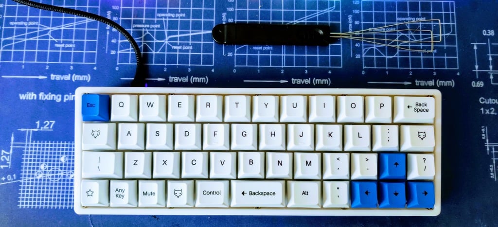
Handwired or GNAP 2.0 mechanical keyboard 3d printed case
thingiverse
This is a case for the GNAP2.0 pcb of 40percent club, you can find more information about the PCB here: http://www.40percent.club/2016/10/gnap-20-plateless.html and here: https://git.40percent.club/di0ib/tmk_keyboard/src/branch/master/keyboard/gnap/pcb I downloaded the Gerbers from di0ib's github, sent them to JLCPCB and got back 5 PCBs for 10 bucks plus shipping (actually it cost way more than the shipping than the PCBs) Meanwhile I designed and printed this case. You will need at least a 235x235 bed to be able to print them in one piece. I have an Ender 3 pro. The design includes already the brims for better adhesion. Building this keyboard is a bit tricky. You must: 1. Cheat with your slicer, make it think your print bed is 235.2x235.2, then find the right 45° print angle and be sure the print bed is placed in the right way so all corners of the case fall inside it. After you have printed the case, print 10 spacers, or you can use any other M2x3.5 spacer. You will need 10 of those. 2. Solder the diodes and the ProMicro in the PCB (I went with only one Pro Micro, so no resistors nor LEDs). Use sockets for the ProMicro, do not solder it directly to the PCB, or you will not be able to solder the two switches below it. 3. Place the switches in the printed plate. 4. Place the screws in the plate. You will need 5x M2x12 screws for the upper row and 5x M2x10 screws for the lower row. Use screws with a relatively small head, or you will have troubles. I used these ones: https://www.amazon.com/gp/product/B074GZ46MV/ref=ppx_yo_dt_b_asin_title_o00_s00?ie=UTF8&psc=1 5. Place the spacers in the screws, carefully put the switch pins in the PCB and solder the switches. 6. Place the USB-C daughterboard in place with two M2x6 screws. You will need exactly this one: https://www.banggood.com/TYPE-C-Female-Test-Board-USB-3_1-with-PCB-24P-Female-Connector-Adapter-For-Measuring-Current-Conduction-p-1551934.html?rmmds=myorder&cur_warehouse=CN or you can alter the design to accommodate the one you have. 7. Cut a Micro USB cable to the right length and connect it to the USB-C (google the diagram for the connection: you will need to solder GND, VCC, D+ and D- to the respective pads on the daughterboard). If you are good at soldering, instead of using a USB cable, you can pick up the D+ and D- signals from the two 220ohm resistors on the ProMicro, get the Vin on the voltage regulator, GND pin and bring the four wires to the daughterboard. 8. Flash your ProMicro with QMK's UT47.2 default profile, or anyone that suits you. Be sure there is a RESET command in your keymap.c, to be sure to update again the firmware in the future without having to open the case. 9. Optional: fill the bottom of the case with silencing foam from Home Depot, to make the typing sound less hollow. 10. Place the captive M2 nuts in the bottom of the case. I suggest you put a small piece of tape to close the gap and prevent the nut from coming out when you tilt the keyboard, or screwing in the top will be a frustrating experience.
With this file you will be able to print Handwired or GNAP 2.0 mechanical keyboard 3d printed case with your 3D printer. Click on the button and save the file on your computer to work, edit or customize your design. You can also find more 3D designs for printers on Handwired or GNAP 2.0 mechanical keyboard 3d printed case.