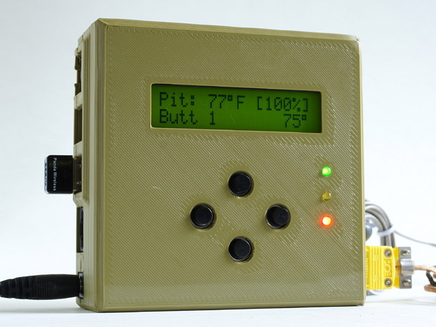
HeaterMeter v4.3 Customizable Case
thingiverse
The official protective enclosure for HeaterMeter v4.3 BBQ grill controller. Print your own! This customizable case holds a HeaterMeter and Raspberry Pi, tested with B+ and Pi 3, but should fit A+, B+, Pi 2, Pi 3B, Pi 3A, and Pi Zero. NOT Pi 4. Updated: 2019-Sep-03 Move LCD/buttons/LEDs 0.695mm Remove Pi alignment nubbies Expand Pi ethernet jack cutout interior 0.5mm Add option for mouselegs Default wall=2.0mm, wall_t=1.45mm USB pillar width 2.0mm -> 2.2mm Interior fillet from 1mm chamfer to body_corner_radius/2 round Don't cut out pic_ex and then rebuild it, just cut less (makes Pi ethernet jack area smaller) Increased case height from 32mm to 32.5m, length +1mm, other sub-mm tweaks (5e107f7) 2018-Nov-29 Less round nuttraps for straight-only overhang Raspberry Pi 3A+ option Corner radius now a function of wall thickness for consistent thickness at corners Removed pin cutout by LCD, space is never needed 2018-Apr-05 Fix for incorrect LCD view area offset. LCD anchor point now calculated from PCB location (moves LCD down ~0.5mm) Add hidden option to generate a LED soldering jig 2018-Feb-02 Offset HeaterMeter 1mm from front edge of case Refactored some offsets to use their real values Adds configurable parameters for corner radius and chamfer height. Corner radius must be > 0 even if it is 0.01. Adds configurable parameters for wall thickness and face thickness Removes mouseears Default wall thickness is now 3mm (up from 2.82mm). 2016-Sept-23 Replace square edge fillets with new continuous bead chamfer and increase roundness of corners Fix guide lips not being attached in STL export Added USB pillar reinforcements Reduce wall thickness 0.14mm (2.82mm now) Interior filleted to add corner strength Case split at different height for probe vs rest of case to make USB pillars less torqueable 2016-Sept-16 - Adds optional corner mouseears 2016-Sept-09 - Adds additional lips on sides to aid in alignment Print Settings Printer: C-Bot Resolution: 0.3mm Infill: 15% Notes: Do not print with support, no angle is greater than 45 degrees and support could fill the nut traps which would make them really hard to clean out. Be sure your slicer fills the posts between the USB jacks and the locklip with something (infill or solid) or they will be brittle. Walls should be an even multiple of extrusion width to be solid. Examples: Extrusion Width of 0.7mm x 4 = 2.8mm wall Extrusion Width of 0.7mm x 2 + External Perimeters 0.6mm x 2 = 2.6mm wall Perimeters 0.5mm x 4 = 2.0mm wall or 0.5mm x 6 = 3.0mm wall Post-Printing Hardware Attach both halves together with 2x M3 nuts and 2x M3 socket cap screws, 25mm-30mm. The case has a feature to help align the nuts. Insert them into their holes from the side until they jiggle freely (a small screwdriver can help them get into the cavity). Before closing the case, insert your bolt down into the nut and tighten it a few turns. Press down to trap the nut in the tighter recess below the slot (see the cutaway image above) until it snaps into place. Then back out the screw and it will remain aligned with the screw hole. Keeping the case tilted so that the probe side is up also helps to prevent them from wiggling out of alignment before you can get the screws in.
With this file you will be able to print HeaterMeter v4.3 Customizable Case with your 3D printer. Click on the button and save the file on your computer to work, edit or customize your design. You can also find more 3D designs for printers on HeaterMeter v4.3 Customizable Case.
