Heirloom Neon Blinking Lights
thingiverse
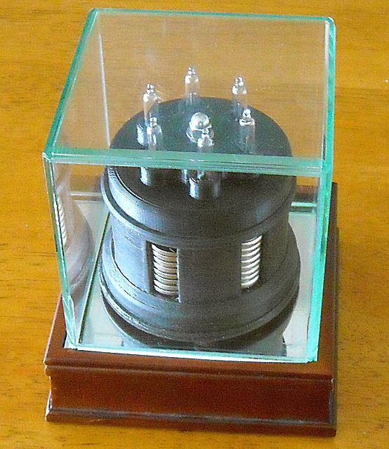
This project requires soldering so it may not be quite as simple to build as it may at first appear. However if you do choose to build one it can be visually rewarding and will last for many, many years. Because of the nature of neon bulbs, and assuming that the capacitors are chosen carefully, the battery pack should last for basically its shelf life which could literally be measured in decades. Hence the "heirloom" in the project name (and it sort of looks old-fashioned anyway). If designed with LEDs it would be more complex to build and battery life would be weeks or months instead of decades. Neon lights still have a place in the present day. **Batteries-** The CR2032 batteries I used here can be obtained from various sources including the one mentioned below for about $15 for 50 batteries (you actually need only 48 of them for this project). Although at retail prices they would be ridiculously expensive, they are in fact good and economical choices when purchasing in bulk. CR2032 batteries are one of the most commonly used sizes of coin cells, so they are readily available and should remain available long into the future. They are lithium batteries which have a high energy density and a very long shelf life, and in this application they should last for their shelf life or close to it. The actual array voltage is around 154 volts when the batteries are factory new but drops a bit to 144-146 volts and stabilizes there for the service life of the cells. **Neon lamps-** I used common A1A neon bulbs (see below) but if you prefer higher brightness versions or smaller bulb sizes, they are easily obtained as well. A1A bulbs fire at about 90 volts and release at around 55 volts. Higher brightness versions will tend to fire at higher voltages but with the battery source voltage of ~150 volts it will not matter. **Capacitors-** I used 0.22 microfarad 250 volt film capacitors for this application. They have low leakage and losses which is important for battery life and because of the very high series resistances involved. I used these particular versions to keep the energy consumption and bulb stresses low, but if you want higher brightness flashes you could use higher capacitance (as long as they physically fit into the cavities). Whatever you use, they should have a rating higher than 150 volts DC in case a lamp fails to fire. **Resistors-** Nothing critical about them other than their high resistances. I used pairs of them in each leg (one on either side of the capacitor) to be able to use common values. I built two of these blinker assemblies, one using 10 megohm resistors and the other with 22 megohm resistors. This yielded individual bulb blink rates of about 1.4 and 2.8 seconds. Personally I prefer the slower version using the 22 megohm resistors, but either way the battery life should be measured in decades. **Wiring-** The insulated portions of the wiring should be rated for at least 150 volts (obviously) but can be very small gauge. I used 24 gauge insulated wire simply because I had it on hand, 28 gauge would have been fine. In the base (under the batteries) you wire between adjacent screws in pairs as shown in one of the marked up renderings. Important- connect these pairs using either solder as wire (to act as fuses) or actual fuses (like 1A Pico-fuses). This is because if you would happen to short out a couple of stacks these little batteries can pack quite a punch current-wise. You could also use a single strand of very fine wire such as extracted from a finely-stranded wire bundle. But thin solder which will easily and safely melt (or an actual fuse) would be better. The bottom cover will contain the melted wire or solder without harm. On the top, wire the springs in cross-pairs, **NOT** adjacent pairs, again as shown in the marked up renderings and photos. This is so that no matter how you orient the top to the base you should not be able to short out any battery stack pairs. **Assembly sequence-** 1) Wire the bottom piece first. 2) Place the battery stacks into the cavities being careful to orient them per the polarity markings in the bottom of each cavity. **It is highly advisable** to use a dab of grease (dielectric preferred, but Vaseline is OK) on the flat screw tops to exclude oxygen and dirt from the atmosphere. 3) Fasten the middle cap over the stacks using the long screw and a nut. No need to tighten very tightly. 4) Solder the bulb wires and capacitors in pairs and trim any excess wire lengths. 5) Wire and install the cross-pair spring connections and individual springs into the upper cap as shown. 6) Next wire one side of the capacitors through resistors into the recessed cavity and tie all their ends together into a common rail as shown (refer also to the schematic). 7) Now connect one of the individual springs to the recessed cavity resistor common rail. 8) Place a layer of tape strips (such as electrician's tape) over all of the recessed connections. 9) Wire the other side of the capacitors through resistors and tie their ends together into another common rail above the tape strips as shown. 10) Connect the other individual spring wire to this top common rail. 11) Check with an ohm meter to be sure that the two individual springs are not shorted together. 12) Lower the assembled cap onto the pre-assembled battery array, inserting the spring tips through the holes in the middle cap. 13) Fasten the top cap down using an acorn nut and washer or similar. Do not overdo it. 14) It may take as long as 10-15 seconds for the lights to start blinking initially because the capacitors must charge all the way to 90 volts for the lights to trigger. But after that they should settle into a random blinking pattern. **Other assembly notes-** Use flat top screws in the base for the lower contacts so that the batteries will not be overly mechanically stressed as they would be if using button or round top screws. Use springs that will easily fit into the recessed cavities but which are not too loose (so they won't fall out), refer to the component list for suggestions. Because springs are not easy to solder to, I stripped about 3/4" of insulation from the ends of the wires and wrapped the wire into the springs (see photos). Then I engaged the insulated portions back into the springs. They are quite secure that way and make good contact. The center bolt is a 2-1/4" long 8-32 all-thread screw, but an M4 will work nicely. I used a stainless steel acorn nut on the top end for cosmetic purposes, it is not critical. There is a hex nut (partially shown in the battery stack assembly photo) that holds the middle cover and base together to contain the battery stacks. The base cover is held in place using #4 x 3/8" sheet metal screws. Flat top screws are preferred although I only had pan head versions on hand. Both will work fine. The flat top screws used in the base for bottom contacts are M3x10mm with KEPS nuts to grip the plastic and the solder that I used as fusible elements, but 4-40 versions will work fine (see rendered views). Make sure that the screw heads stand proud of the interior bases of the cavities so they will contact the batteries. Use stainless steel for these if at all possible so they will not corrode. The slots in the sides of the base are primarily there to be able to place the batteries into the stacks, though they do add visual appeal. I used a softball case to contain the assembly, not only to keep it from collecting dust, but to discourage little fingers from touching it. Softball cases are slightly larger than baseball cases. There is upwards of 150 volts available if certain places are touched, which though unlikely to actually be dangerous, could startle someone. So if you are not going to place the assembly under a cover as I did, trim some pieces of thin plastic or paper as closure strips and thread them around the batteries once you have placed them into the cavities to shut off finger access. **Materials-** The electronics parts are available from many sources, but I purchased mine from Digi-Key (www.digikey.com). Lamps- A1A (these are standard neon lamps with no series resistors) Capacitors- 224MMR250K (0.22uf/250VDC film capacitors) Resistors- CF14JT22M0 (22 megohm 1.4 watt resistors) Batteries- CR2032 (3.2 volt lithium cells, 20mm diameter, 3.2mm thickness) Total cost for electronic parts- around $22 The springs are 4.5mm OD (~3/16") and are 20mm in length (~3/4") and may be obtained from hardware stores, old ballpoint pens, or McMaster-Carr 1986K327 (about $7 for a pack of 6 springs) (www.mcmaster.com). They do not need to have much compression pressure, they only need to contact the tops of the battery stacks reliably. All other hardware should be commonly available at hardware stores or McMaster-Carr. The softball case shown was purchased on sale at Michael's Crafts, but almost any crafts, hobby, or sporting goods store (or similar) will have them or something very much like them. Be sure to get a case that is at least 4.2" (110mm) in all directions inside. **Thank you for viewing this project and I hope that it was entertaining. If you choose to build one I hope you enjoy it as much as we enjoy the ones I made.**
With this file you will be able to print Heirloom Neon Blinking Lights with your 3D printer. Click on the button and save the file on your computer to work, edit or customize your design. You can also find more 3D designs for printers on Heirloom Neon Blinking Lights.