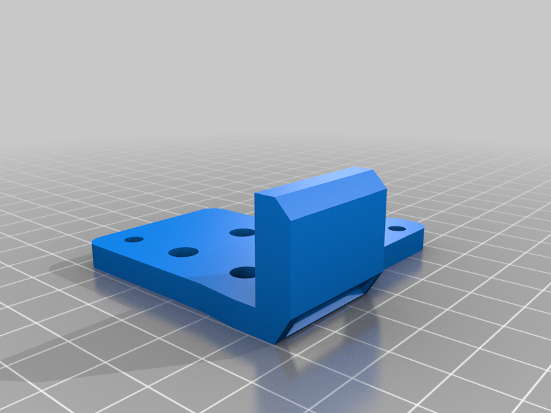
Hevo Direct Drive Mount
thingiverse
This is a remake of Scott_3D (https://www.thingiverse.com/thing:2254103) and AMIDE (https://www.thingiverse.com/thing:4210434) mounts for the Hypercube Evolution printer extruder. I was wanting to mount my TriangleLab Direct Drive extruder, but I could not find a mount that I liked. AMIDE came close but she had the BLTouch mount on the left and I wanted to keep it on the right as it currently is. So, I took AMIDE’s and Scott_3D’s mount and combined them into one single mount. If you use Scott_3D mounts, you will be able to reuse the X-carriage mount for this to attach to. This has taken several months to work out the kinks, but I think I have a good working model now. However, here are a few things to note: Prior to any assembling of any of the parts, I have found it is best to pre-thread all of the screw holes with an M3 screw. I have deliberately made these holes a little smaller to give the screws something to bite into. By threading a screw in prior to assembly, it will make assembly a lot easier. Also, pay special attention to the screw holes for the 30x30 fan. These are right on the edge and they don’t span very deep so you want to make sure your screw isn’t too long and come out the other side. Also, gently tighten all screws. This is just plastic and the holes can become easily stripped. I also didn’t specify what screw length goes where. I kinda think that y’all should be able to figure that out. You just need enough screw to bite and hold without coming out the other side. You will need to make adjustments for homing. With this mount, you will lose a little print area on the left, right and front of your printer. Truthfully, it won’t be that much, and you probably already lose that amount with the bed clamps. If you have a filament out sensor, and it homes to the front right, you’ll need to make changes in your firmware to accommodate for the pancake stepper motor. First, with the 30x30 E3D fan mounted on the left, there is not enough clearance when the X-axis homes so it will likely crash into the Z-axis mounts. I solved this by adding a small extension to the flag to trigger the sensor sooner. I just got a piece of a scrapped print, cut a little chunk off of it, and glued it to the existing flag. If you choose to do this make sure you use a black piece or paint it black so it will register with the sensor. You might have also noticed that I also moved the Optical Sensor out from the body of the extruder mount to help with this clearance. Also, the Y-axis sensor needs to be moved back (closer to the center) to give clearance for the part cooling fan from crashing into the front extrusion. For the filament-out sensor, you’ll need to go into your firmware and adjust the amount of clearance to the X- and Y-axis so it won’t crash when homing to purge the filament. I made my distance at 20mm each. It gives plenty of clearance. You’ll also need to adjust the amount of filament Marlin will purge when changing filament. I think I changed mine to 20mm also, but I can’t remember right of hand. More information for these setting can be found here: https://marlinfw.org/docs/gcode/M600.html Also, Michael of Teaching Tech has a great video on YouTube on what needs to be changed/adjusted in Marlin to get this to work. His video is for a fresh install of a filament-out sensor, but he does take you to all of the places in Marlin that you’ll need to make your adjustments. You can find his video here: https://www.youtube.com/watch?v=gwHpXaj_6xE Another change you’ll need to make is the number of esteps for the direct drive. This can be done in Octoprint through Settings --> EPROM Marlin Editor Plugin --> Steps. On the far right, under Extruder, change this value for the new Direct Drive. I use 415 and it works great. Be sure to test your esteps by extruding 100mm and measuring the amount that was extruded. More information on this is all over YouTube so you can Google it to find the necessary information on checking and adjusting your esteps. Finally, you’ll need to adjust the voltage for the extruder driver. With the Bowden I had it set for 1.0v but with the direct drive, I dropped it down to 0.5v and it works great. I originally had it set for 0.8 but the pancake motor ran way too hot and the print quality suffered greatly. Once I dropped it down to 0.5v, the motor is barely warm and the quality is superb! I printer with PETG, 6 top and bottom and shell, with 20-30% infill. The more layers and infill the heavier but you want this to be strong and firm. Use supports but I remove them from the small screw holes because they become a pain to clean out after printing. And I print with the back (the part that gets attached to the existing Scott_3D X-carriage) on the table. I find this gives better quality. I think that about sums it up for now. I have also provided holes in the mount for linear rails but as of yet I have not tested these so use at you own risk. As I said in the beginning, this is a work in progress so there is a chance, albeit a small one, that there would be upgrades in the near future. But keep in mind that his thing ain’t perfect. Not everything lines up just right but it’s close enough and with a little persuasion it will all go together. This version is actually number 12 so it’s been tweaked greatly. I’ve also enclosed a pdf document with assembly instructions. I know – I’m anal… Have fun and if you have any question, just drop then in the comment section. I usually don’t go in and check these but every once in a blue moon but I’ll try to answer when I can.
With this file you will be able to print Hevo Direct Drive Mount with your 3D printer. Click on the button and save the file on your computer to work, edit or customize your design. You can also find more 3D designs for printers on Hevo Direct Drive Mount.