HFT Ammo Box UPS/18650 Battery Pack
thingiverse
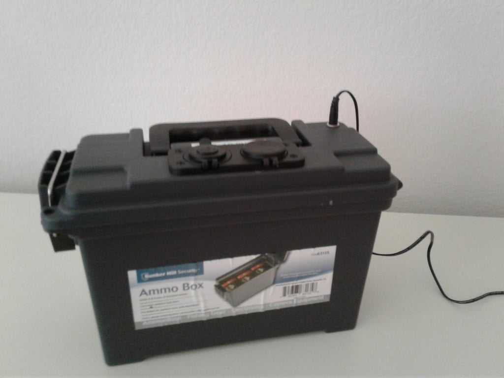
I wasn't sure whether to call this a battery module or UPS because for my application it is both. This is a 3D print design supporting a 3S16P 18650 battery module, which I am using as a 12V UPS for some household "gotta stay on" equipment. It is built inside a Harbour Freight Tools Ammo Box, and includes 3 packs of 16 18650 batteries for a module total of 48 batteries. Each battery is rated at 4 Amp hours, so this should give 192Ah for the module. Each of the packs is 4x4 batteries, with fusible links soldered on each individual battery on the positive end. I wasn't sure if I could fit 4x5 or 4x6, but I decided that the 4x4 design was adequate for my interests. Either of the other 2 choices would have required some major modifications to get the fusible link and bus wiring to work correctly on the positive side. The input to the charger is a power port to a buck/boost converter, which accepts 5V-30V. The output is a 12V power port ("cigarette lighter") and dual 5V USB for charging phones etc. The voltage regulator is programmable, and needs to be set to 12.4V output for the Battery Management System ("BMS") on the battery pack. Many choices of wall wart will work to charge the system, so I won't list any in the parts list - choose your own, and set the battery charge voltage and current on the buck/boost converter to match the power supplied. Since the input voltage is variable, you could probably use a solar charger as well (don't let it exceed 30V). The wall wart I use provides 12VDC at 2A, so I have the buck/boost set to charge the battery at 12V/1.5A. I am only using a maximum of about 3A load when the battery pack is in use, so I used standard 2.1mm power connectors internally. The hardware would support greater loads - If you have higher current needs, XT60 connectors should be used within the box instead. Caution: When soldering the fusible wires and connecting the packs together, remember that the batteries are live. Don't let any of the wires touch each other or things will short, getting wires hot and/or blowing the fusible links. Cover all exposed wires with tape except the one or two specific wires you are directly working on. Don't connect the cells into packs without a fusible connection on each battery cell or you will eventually have a bad day. Caution: Make sure that the batteries in a group are matched together with similar characteristics. Test with a volt meter, even for brand new batteries. Don't mix brand names, cell capacities, different Amp-hour ratings or old/new cells. I purchased all of mine brand new from one source, one brand name, the same voltage/current/Amp hour specifications and tested the voltage on every cell before putting into a pack. The batteries were voltage matched and assembled into the 18650 Caps. Each cap is the same 3D print design but it is worthwhile to print the positive and negative ends in a different color (eg. black for negative and red for positive). On the positive post of the batteries, the fusible links were soldered to a 14 gauge bus wire, which was also used for inter-device connections. The nickel strips were soldered to the negative end, with a 14 gauge wire for connections. Because the fuse wire is smaller and wants to get into everything, I found it easier to assemble by soldering the positive end with the fuse connections first. Each pack of 4x4 batteries was wrapped in duct/duck tape, then the 3 packs were placed in the 3D printed sleds and wired together and into the BMS card with 14 gauge wire. When making all the inter-pack connections, all exposed wires were covered in tape except the one or two I was currently wiring together. Power connectors were attached to the BMS module, a final voltage check and charge test were performed, then the whole module and BMS board wrapped with duct tape, with only the power connectors sticking out. Write "This side up" on one of the sides 90 degrees to the BMS card surface so that you don't mount the BMS and connections on the top surface of the module when in the ammo box. 3D print items: 18650Cap.stl - 6 required (3 black, 3 red) BatteryPackSledSimple.stl - 2 required BatteryPackSledWithBMS.stl - 2 required ChargerMountPlate.stl - 1 required PackRetainerCrossBar.stl - 2 required PackSpringRetainer.stl - 1 required Each is PLA and can be any color, except the 18650 Caps should be 3 black and 3 red. If the PackRetainerCrossBar is printed upside down it will not need supports. Supports are needed for BatteryPackSledWithBMS, ChargerMountPlate and PackSpringRetainer. The PackSpringRetainer should print on its side. The Battery Pack Sleds are long and will need to print diagonally on the bed surface. I printed them separately on my Ender 3 Pro; I'm not sure if they would print together. The parts list for the project as I built it: * Ammo box - https://www.harborfreight.com/030-caliber-ammo-box-63135.html * 18650 batteries - available anywhere. I got mine brand new on ebay. * 14 guage wire - available from any electrical supply store, 3 feet or less * Fuse Wire - https://www.amazon.com/gp/product/B01M0AXONC * Nickel Strip - https://www.amazon.com/gp/product/B07BRDZNVM * 3mm Nuts Bolts Washers - https://www.amazon.com/gp/product/B07NV6GVVR * Buck/Boost Voltage Converter - https://www.amazon.com/gp/product/B081YQQVHC * 3S Battery Management System - https://www.amazon.com/gp/product/B07JMY631D * 12V Power Port and USB power - https://www.amazon.com/gp/product/B087F6BGRC * Power Connectors - https://www.amazon.com/gp/product/B07C7VSRBG * Panel mount power connector - https://www.amazon.com/gp/product/B08272H1SR
With this file you will be able to print HFT Ammo Box UPS/18650 Battery Pack with your 3D printer. Click on the button and save the file on your computer to work, edit or customize your design. You can also find more 3D designs for printers on HFT Ammo Box UPS/18650 Battery Pack.