HicTop Prusa i3 Auto Bed Leveling Sensor Mount
thingiverse
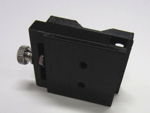
This is a sliding mount for the auto bed leveling sensor type SN04-N used on some Prusa i3 3D printers. This sliding mount is much easier to adjust than fixed mounts and is easy to make from commonly available screws. This mount can be adjusted by very small amounts making it easier to get your Z height just right for the perfect first layer. The design can be adapted to other printers by doing a new base mount for the base and sliding parts which stay the same. To assemble the mount, you will need a 1.375" long 4-40 screw and a 4-40 nut to create the lead screw. The mount is screwed to the bearing block using 4mm cap screws. The sensor is screwed to the sliding portion using the original 3mm screws and nuts. For convenience I added another members sliding portion design for 12 and 18mm round sensors. http://www.thingiverse.com/thing:1354218 In the Files section of this Thing I have placed a PDF document giving details about how to assemble and install this sliding mount. I designed this sensor mount using TinkerCAD. I allowed some clearance between the slide and the mount but depending the printer used to make the part, that clearance may or may not be enough. This is why I suggest to you sand the part for a perfect fit. Here is access to the part in TinkerCAD so that you can look at it.https://www.tinkercad.com/things/a8XgNPFI4O6-30mmslidingconnectorv3https://www.tinkercad.com/things/4qAJbcP2OjP-30mmslidingbasev3https://www.tinkercad.com/things/acEVQB3GHT9-30mmslidebearing-block-mountv3 Update: Some people are finding that their sensors are not reliable when powered with 5V . I've attached a circuit that I use that allows the sensor to be powered with a higher voltage such as 12 - 24 V and lowers the output signal to 0-5 V for the input to the controller. It uses a blocking diode. When the sensor output is 12-24 V, the diode blocks the voltage so that the controller input is 5 V. When the sensor output goes to 0 V, the diode conducts and the controller input is pulled to nearly 0 V (actually 0.7 V). Print Settings Printer Brand: RepRap Printer: Prusa i3 Rafts: No Supports: No Resolution: 0.1mm Infill: 40% Notes: Black PLA extruder 195c bed 55c on Kapton You will need to do a little sanding to get a smooth sliding action. At least I did on my printer. After you get the slide and base working smoothly, screw the 4-40 nut and the screw to the base. Add a tiny drop of Super glue to the threads and screw the nut so there is no clearance and the screw turns smoothly. Be careful to not get glue on the hole in the base.The bearing block is super glued to the back side of the fixed slide part. Make sure the two cap screw holes are visible(not blocked). The glued assembly is then screwed to the bearing mount using two 4mm cap screws. Attach the sensor to the sliding portion with two 3mm screws and nuts. The nuts fit in the recessed back side of the slide. Insert the slide part into the base and turn the screw until the slide is all the way into the base. The slide is self threading and after a few in and out runs will work great.
With this file you will be able to print HicTop Prusa i3 Auto Bed Leveling Sensor Mount with your 3D printer. Click on the button and save the file on your computer to work, edit or customize your design. You can also find more 3D designs for printers on HicTop Prusa i3 Auto Bed Leveling Sensor Mount.