Hot Tub CnC Machine
thingiverse
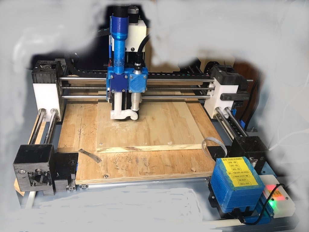
This Router Machine right now holds a flexible Dremel tool with a vacuum pickup to collect the cuttings. But other attachments are possible. Recently, I added larger flexible shaft router capability. It can interface with Foredom General-Purpose Handpiece 1/4" Flex Shaft Rotary Tool - H.44T . This allows for 1/4 inch or 6.25 mm router bits. The machine uses a total of six,12 mm rods as linear slides on the x and y axes. I purchased a Befenybay 200mm 4080U Z-axis Screw Linear Actuator for the z axis from amazon. The stepper motors and the anti-backlash nuts are attached with 150 mm long m3 threaded rods and nuts. The bolt goes all the way thru the part. Most critical parts bolt all the way through as well. To accomplish this I cut the M3 threaded rods from 150 mm long m3 threaded stock to the proper length. Then I saved the cutoffs for parts that required a shorter length threaded rod. Any where that I’m not bolting all the way through a part, I'm likely using one of those brass threaded inserts that can get melted into the part. I purchased a cable track as printing one seemed a little time consuming. Opposite the X and Y axes stepper motors on the 8mm Acme screw is a thrust bearing setup and printed thrust bearing cartridge. This cartridge allows you to set the backlash for that axis. Print Part 31 and 32 with 100 percent fill and sand the face of it a little at a time until you have the desired backlash. Part 31 and 32 are the parts that actually determine the amount of backlash. Part 39 is a bearing race holder. The bearing race is a suitable washer that fits tightly into part 39. With the washer in there, I sanded the part till the washer was shiny and flush with the plastic edge. Part 36 is the inside race holder. It also gets a washer and gets sanded, but it slides onto the acme lead screw and fits tight onto a shaft collar. The set screw on the collar sticks out a little and there is a little notch in the part to accommodate that set screw. See the sixth photo. It shows part 39 on the left side of the picture and two of part 36 facing away from each other on the right side of the photo. There is another part 39 off to the right that can’t be seen because I had to crop the photo to get it below 500 kilobytes. It's these parts that make up the backlash cartridge. They all sandwich together and 4 M3 threaded rods keep everything tight together. If you assemble the end opposite the stepper motor and there is no backlash then you haven’t sanded part 31 or part 32 enough. You can stop sanding it when you assemble it and you can detect backlash at least 0.001 inch and not more then 0.003 inch. The face you are going to sand is the face that was up when you printed it. I’m using regular steel m3 nuts and stainless threaded rod so the nut will just crack if you over tighten it. The nut will continue to tighten without a reduction in backlash if its tight enough. Also, any part that holds a bearing race should be sanded so as to not allow plastic to ride on plastic. You want those needle bearings to spin true with low friction. To check the tolerances, part 28 is the backlash/dial indicator tool holder tool. Assembly order is first set backlash at one end, and then install the stepper motor at the other end. Then measure to determine the desired length of 12 mm Rod. Cut this rod, remove the backlash cartridge and stepper motor. Get ready to install the 12 mm rod with bar clamps, and press it into the part. But do think ahead and install all necessary parts on the rod. Finally reinstall the backlash cartridge and stepper motor after all linear rods are installed. Parallel bar clamps were used to press the 12 mm rods into their respective parts. I'll include a photo. Sometimes I was required to hold parts apart from one another with one clamp while using a second clamp to press in a 12 mm rod. I'm using LM12uu bushings throughout, sleeves (Part 27 ,29 and 30) hold the bushings and then the sleeves slide into their respective parts. I’m using a standard CNC shield. The x and y axis limit switches are double ended. Meaning it trips at the x minimum and x maximum. There is just one switch. However, it is activated at both ends of travel. Likewise with Y axis. They use the typical mechanical limit switches commonly seen on 3d printers. Tthe LEDs on the boards for the limit switches work. I power them with the 3.3 volt supply on the CNC shield and ground. The voltage is always there and if a switch develops an open, it will trigger an alarm at the CNC shield. 2n2222 transistors invert the limit switch signal. This solves the problem of the Normally open Vs Normally closed debate. Here is the switch type I used (Logrunner for Arduino IDE Mini V3.0 ATmega328P 5V 16M Micro). These switches work well. Some tend to install them with the lever arm perpendicular to the direction of travel and this results in a harsh impact rather than a gentle activation. The design here uses a gentle activation of the switch. The lever arms are a little fragile and if you accidently bend one it will affect operation so placing a piece of carefully trimmed packing tape over the switch lever so as to prevent the lever from accidently getting bent forward in the wrong direction will prevent this problem. A little slack in the tape allows for normal movement in the proper direction. I noticed when installing a router bit and tightening them down, it's easy to bump the z axis limit switches and bend them. The tape trick seems to have solved the problem. I used 2 separate z limit switches because this allows for greater X axis travel distance. Each z limit switch connects to an optical isolator input just like the x and y. The Z axis signals from each optical isolator connect to a somewhat modified diode OR gate (an OR gate that can work forward and reverse polarity is just a bridge rectifier that is being used as a gate Schottky diodes are used here ). The diode OR gate output signal connects to a 2n2222 transistor. This inverts the signal and the inverted signal connects to the CNC shield. The limit switches use 3.3 volts. The input to the Arduino uno is 5 volts. Using this optical isolator, ( NOYITO 4-Channel Optocoupler Photoelectric Isolator Module Level Voltage Converter Module PLC Signal Converter Module PNP NPN to NPN (3.3V to 5V) again from amazon ) ############# I transition from 3.3 to 5 volts without adversely affecting the operation of the LEDs on the limit switches or the isolator as well as mitigate stepper motor noise. I'll make one of the pictures a schematic. Also, In the firmware I’m running a 350 MS debounce on limit switches. Print 57 is a spring seat for the double the ended limit switch. The springs on the double ended limit switches are the same springs as on the anti-backlash nuts. I just cut them a little shorter to make them fit. The Ideal spring length is decided by cutting is so the lobes on part 58 are held equidistant from the limit switch arms without significant tension on them just enough pressure to allow consistent returnability. Part 20 and part 20.1 are stops for the limit switch rod ends on the Y axes only. They contact part 60 on the limit switch You may discover you like part 20.1 more than 20 as its shape is improved and guarantees your cable track won't snag it. I have several vacuum parts as no one vacuum part seems to work well with all types of router bits and projects Dremel uses 1/ 8th inch bits and some vacuum apparatuses are designed for 1/8th inch bits. Others are for 1/4th inch bits. Very little vacuum is needed if you are making a pc board. Other vacuum parts are designed for maximum depth and large air flow as you can adjust the machine to cut deep by loosening the bolts in part 42 and sliding the entire z axes lower Parts 16 and 17 have a a few attachments designed to conceal wire and hold cable tracks in the correct position giving things a little more professional look and possibly preventing damage from unwanted vibration. I used 22 awg stranded wire for everything in the cable tracks. and soldered the wires directly to the wires coming out of my stepper motors and limit switches. At the top of the z axes is part 2, a box that secures to the back side of the z axes. Its used to wrap up any slack in the wiring so that if I need to resolder a wire to replace a motor or switch will have the necessary length to service and trouble shoot without running a whole new wire thru the cableing tracks. Likewise, at the other end of the wires below part 21 and 35 there is some room to hide a little slack in the wires for your splicing and troubleshooting needs. I did do my wire splices at the base of the machine first and my wire splices at the top of the machine second.This means the majorty of slack is at the far end . There is only need for part 46 , 47and 53 if you Have a Dremel flex shaft . If your going to use a Vevor Flex shaft Mill you don’t need to print them. Instead print 53.1 and a quantity of 2 of 46.1 My preference is that printing part 50 is no longer necessary as part 50.1 works with both Dremel and Vevor Hanging Flex shaft Mill and part 50 only works with Dremel. However part 50.1 is larger. Most parts should be prinable on a 6 inch prusa. the Uno/cnc shield shield base (part 24)may be a bit big. The wire guide on the side of it can be eliminated if your print space is limited . On the z axes each side has part 52 the z axes limit switch holder (makes adjusting the z axes limit switches easier) its held down with m5 bolts about .46 inch long and the limit switches bolt to it with m3 bolts and nuts . the switch has a cover, part 51 . and if you print it in something light colored the LED lights show right threw it pretty well. Same with the optical isolator cover a nice white ASA lets the LED’s shine right threw. But pegt is my preferred plastic for all other parts . This is mostly due to its minimal shrinkage. I’ve done a dozen carvings in hardwood and 2 in aluminum with this Machine. So far, the machine seems to work excellent. I Have a Torchmate CNC at home in addition to this. This 3d printed machine Is more accurate and better suited for finer detail. Its strong enough to last. Cutting area is 335 by 335 MM (13" by 13"when I back 4mm off the limit switches (a setting in the GRBL firmware). Larger cutting areas are possible with these same components however I think rigidity is an important consideration when it comes to a design that uses plastic . many small sized machines are a fast print design at the expense of rigidity. This machine design is capable of cutting bigger if I use reference pin holes allowing me to reposition the work piece without compromising rigidity . I have a spoil board on top of the 20 by 20 rails that can be removed . I can adjust the Z access height to cut lower then the spoil board , a really convenient feature if say you wish to put a drill press vice below the spoil board and just keep it there for more detail oriented projects pc boards and such . This adds to the machines versatility. It so far has the accuracy of an ink jet printer and the strength of an arbor press. I’m very pleased with the first projects I’ve completed with it,
With this file you will be able to print Hot Tub CnC Machine with your 3D printer. Click on the button and save the file on your computer to work, edit or customize your design. You can also find more 3D designs for printers on Hot Tub CnC Machine.