How to attach a LJC18A3-H-Z/BX capacitive probe via optocoupler to Creality Ender 3 (and other printers)
thingiverse
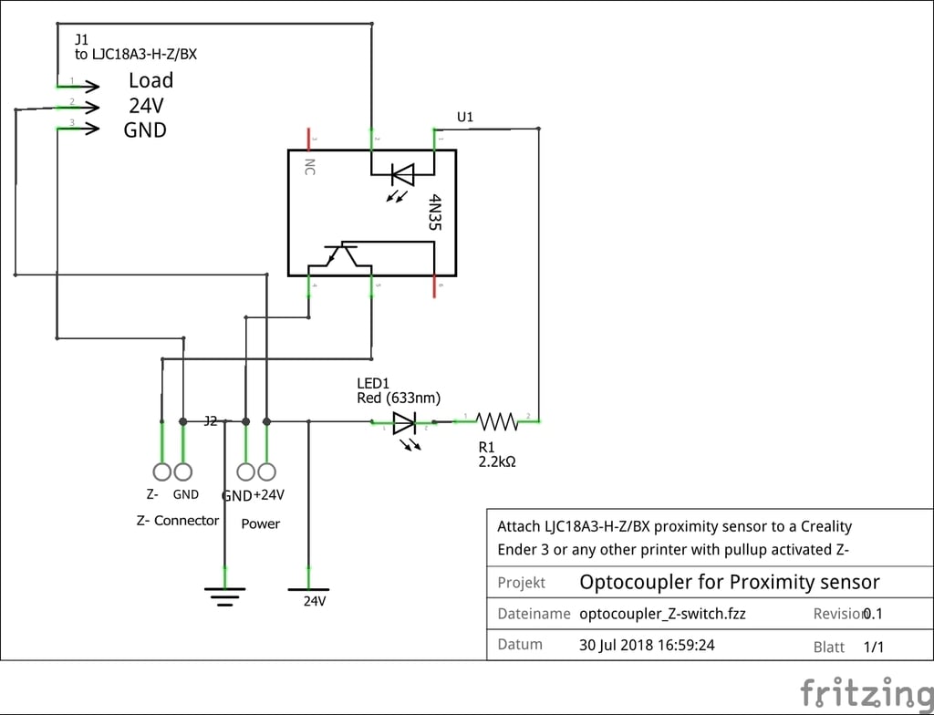
This is a quick description on mounting the LJC18A3-H-Z/BX on an Ender 3 as an alternative to ready made kits available on the market. You need some soldering skills and a bit of electro-technical knowledge. If you don't know what you are doing, buy the kits!! I have deliberately not attached a PCB layout because this is so easy to set up on a prototype board - no PCB needed! And it's more fun! ;) Warning: you need to flash a boot-loader on your Creality Melzi board. You will loose your original firmware. You need to flash an alternative one: https://www.th3dstudio.com/knowledge-base/th3d-unified-firmware/?seq_no=10 NO RESUME ON POWER LOSS ANYMORE!! So first, we start getting the sensor. EG: https://www.aliexpress.com/item/High-Quality-LJC18A3-H-Z-BX-1-10mm-Capacitance-Proximity-Sensor-Switch-DC-6-36V-300mA/32828750563.html?spm=a2g0s.9042311.0.0.79894c4doK4138 It takes 4 weeks to get it from China. For 3 bucks more you will also get in on Amazon. While you are waiting for the sensor, print your Petsfang including the 18mm mount for ABL-Sensor: https://www.thingiverse.com/thing:2759439 I just love this piece of engineering art! Stick with the stock fan option, to keep it cheap and quiet! Now you can put together your tiny PCB. You need an optocoupler (EG: https://www.aliexpress.com/item/20pcs-4N35-EL4N35-DIP-6-new-original-Line-6-foot-Optocouplers-ORIGINAL/1813218893.html?spm=a2g0s.9042311.0.0.27424c4dY1X6CX then you have more than you can eat!) a resistor 2.2kOhm, a LED 5mm/3mm any color, a two pin connector https://www.reichelt.de/platinensteckverbinder-gerade-weiss-2-polig-ps-25-2g-ws-p14825.html and two three pin connectors https://www.reichelt.de/platinensteckverbinder-gerade-weiss-3-polig-ps-25-3g-ws-p14827.html? . Build your PCB according to the circuit diagram. Pictures give you an idea, how to position components economically and how to solder. Beware: This circuit is for boards that provide a Z-switch-Input with pull-up. So if you test the PCB and you want to see the signal on the optocoupler's output toggling, you either need to attach it to your board or solder a 3k3 -10k pull-up resistor from Z- to 24V. When you have the sensor attached and it toggles when touching the head, you then should see the LED toggling and the output voltage on Z- should alternate between 5V and GND (board attached) or 24V and GND (pull-up resistor soldered). DON'T FORGET TO REMOVE THE INTERIM RESISTOR PRIOR TO ATTACHING YOUR CONTROL BOARD. YOU MAY FRY THE INPUT WITH 24V!! Remove mains from the printer. Open the power supply and attach two wires to one of the free 24V and GND connectors long enough to reach the control board compartment of the printer. Close the PS and remount it. After having tested it, cut out your PCB and mount it in the boards compartment left to the control board. Connect Z-switch correctly. When you look on your original Z-Switch, the wire facing forward is the Z-, the other is GND. Mount the probe on the Petsfang and do a preliminary wiring. Make sure, the wires are connected correctly! Mine was black: output, blue: GND, brown: 24V. It's normally printed on the label of the sensor! Flash the TH3D firmware with enabled EZABL with Petsfang mount. There are tons of videos, how to do that including flashing the boot-loader. You need an Arduino Uno or a USBAsp for flashing the boot-loader. Heat bed and nozzle to your normally preferred temperatures (I use 205° and 70°). Move the nozzle onto the bed with a sheet of paper underneath. Adjust probe height to about 2mm above the bed. Adjust sensor sensitivity to that it is just switching on at this height. Turning counterclockwise is less sensitive. Home your printer. The sensor should now be in the middle of your print-bed. Lower it with the movement controls until the paper under the nozzle is just grabbing to the nozzle. Now go to your Info screen. Read the Z-value and put it under settings - movement - Z-offset. Save the values! In your start-script, add G29 immediately after G28. This invokes the automatic bedlevelling procedure before the print starts. Try a print and have fun! Wire the printer correctly. Make sure you are not restraining anything from moving free. Use cable straps! Post your make! This is the first version. Please comment so i can improve it over time. Cheers Armin PS: I had to add a file from https://www.thingiverse.com/thing:13053 to make this thing visible.
With this file you will be able to print How to attach a LJC18A3-H-Z/BX capacitive probe via optocoupler to Creality Ender 3 (and other printers) with your 3D printer. Click on the button and save the file on your computer to work, edit or customize your design. You can also find more 3D designs for printers on How to attach a LJC18A3-H-Z/BX capacitive probe via optocoupler to Creality Ender 3 (and other printers) .