HP Jornada nostalgia palmtop
thingiverse
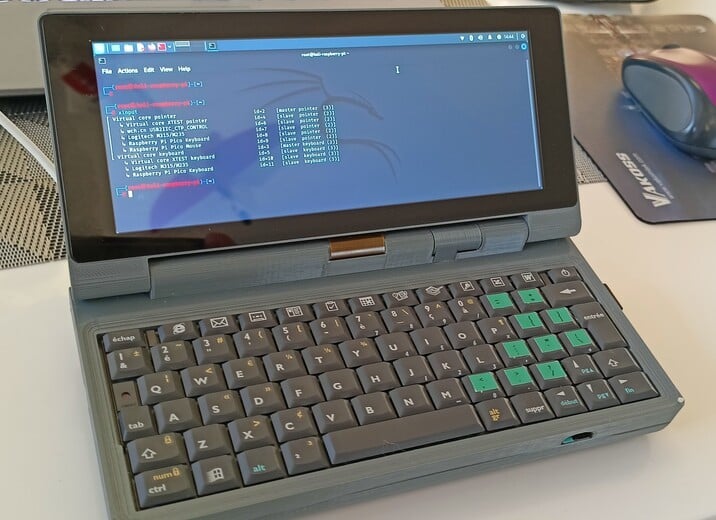
Have you ever dreamed about modern HP Jornada (or Psion) palmtop? You probably not since you can buy one like Gemini PDA but we are on the website where people do things, not buy. So i did it for you. Having a spare keyboard from HP Jornada 720 (french version - unfortunatelly for me - that's why there are those ugly stickers) I've decided to build a palmtop around it. This keyboard is very convenient and flat as a part so final product should not be much more thick that original HP Jornada (I wish). I've been also looking for the LCD display that has the same outline and proportions as Jornada has and found one at our Chinese friends shop. My goal was to let people build this thing with as little efford as possible. So no gluing, no fileing, no dissasembling things (like connectors) from Raspberry. Unfortunately we have to solder few things, but hey, we are at least rocket scientists here. There are few versions of palmtop body prepared: for RPi 3A+ with camera and no camera, Zero W / Zero W2 (no camera). If you plan to initially not add camera you can print a blanking hinge part and replace it later with the one that holds the camera module. My version from the picture has RPi 3A+ inside and is powered by Kali Linux. Before you start to buy anything and build it - read all description. I'm not telling you how to 3D print parts and clean it. You know it. BOM: '1. RPi 3A+ / Zero W /Zero W2 (and similar clones that have the same outline as Zero), microSD card, '2. Raspberry PICO working as keyboard martix USB HID device (CircuitPython code + connection explanation below), Aliexpress parts (you can find just copying description to Aliexpress): '3. 2x 18650 batteries, '4. FFC / FPC 24 PIN 1 mm / 2.54 mm connector board module, '5. 2x USB female sockets (PCB mount 90 degrees), '6. USB2.0 Expansion Module HUB Concentrator module (PCB), '7. 10x15 mm rocker switch, '8. 1A 18650 Lithium Battery Charging Board Type-C, '9. PAM8403 micro audio amplifier 5V module (PCB), '10. 2x 3.5 mm audio jack plugs (to extend audio socket from LCD PCB to the body), '11. 3.5 mm TRRS audio socket (as above), '12. 20 mm 8 Ohm speaker (as flat as possible, preferably 3 - 4 mm), '13. RPi small processor radiator (with glue), '14. HDMI male - male flat cable (FPC ribbon) 10 cm with short straight plugs, '15. 6.86 inch LCD IPS display for Aida64 with separate driver board via FPC ribbon, '16. INA219 (not yet connected by me) to measure current and voltage of batteries, '17. 3x micro USB plug, '18. MT3608 DC Step Up Voltage Regulator Module 2A (with potentiometer, flat version), '19. RPi camera. This is the special version of the camera called "spy" camera with long, flex cable. It should have a connector suitable for the version or RPi that you'll use. Non electronic parts: '20. 6 mm diameter rod (Carbon fiber, alluminium, plastic, whatever). For "no camera" body 180 mm long or for "camera" version 2x 40 mm, '21. 2x 5 mm sections of flexible filament to create "bumbers" between the main body and LCD screen. There are two holes on body's corners that shoiuld be drilled to 2 mm diameter and bumpers can be glued inside. Notice it on pictures, '22. 4x self-adhesive anti-slip pads (5-7 mm diameter), '23. 3x M3 brass knurled melt insert / nut (not really needed, but makes the screw holes robust, '24. 3x M3x4 screws for battery case. Screws should have as small heads as possible, preferably 4 mm diameter, '25. M3x8 for USB sockets bracket, '26. 2x original Jornada screws (they are all the same), '27. 2x M2.5x3 for RPi fixing. I've used only one since the second one is almost impossible to screw in. Here are the links to Tinkercad projects where you can copy and modify it for your needs. https://www.tinkercad.com/things/ev32714gk7f https://www.tinkercad.com/things/fgnbDQ2R2FM Since this is a work-in-progress project it is not yet fully finished. For example I need to add INA219 to measure voltage and current of batteries and write some code to handle it. The same for the camera module. I've tested if the whole thing is not overheating and it looks like not, there are two vent areas at the bottom that are enough for ventilation. Soooo... How to build it? First of all - make sure, that the mainboard and system that you plan to use is able to drive 480x1280 display resolution! I'm sure, that RPi equipped with Raspbian and Kali is able to. But for Banana Pi, Radxa Zero and something like this - I don't know. Check it. OK, let's go. Every electronic circuit that you are building should be finally insulated using adhesive tape, heat shrinkable sleeve, etc. All this crap goes directly in the palmtop belly without any support so this is a good recipe for short circuits. First connect 4. (item from the list above) to the keyboard and solders 24 cables between it and 2. Connect 2. to the computer, program it using CircuitPython, test if it works as HID keyboard with regular computer. Use this tutorial if you have questions: https://learn.adafruit.com/circuitpython-essentials/circuitpython-hid-keyboard-and-mouse The code below is a raw version so do not expect miracles: it does not handle ghost keys, to many keys pressed at once is a killer for it, etc. If you want to improve it - please do and post a solution in comments, I'll apreciate it. But at least my code works for now. Finally fix the PICO and connector at the bottom of the keyboard with double side adhesive tape, cover all this with the insulating tape, including bare metal of keyboard's bottom. Build the USB hub. Solder wires, 2x micro USB plugs (LCD, RPi PICO/keyboard), leave 2x female USB sockets unsoldered (it will be soldered later). Solder it directly to RPi USB pads via cables since there's no room for regular male USB plug to be connected to RPi (if you are able to find such short plug, please let me know). The positive 5V of USB HUB connects directly to +5V of power supply that we will build in the next step. RPi has current limit for USB so it's better to power USB devices directly. Insulate everything. Power supply consists of 3., 8. 7. and 18. The charging module is mounted upside down for two reasons: ventilation and LED visibility through external body hole. Connect it all using rather thick wires. Charging module + and - are connected directly to two parallel 18650 (so it has 4.2 V, NOT 8.4). Minus cable from the charger goes to switch, then to the MT3608 DC Step Up Voltage Regulator. But not solder the switch yet - it should be done during the assembly in the case. The rest can be soldered before, there are special holes in the case to mount it already assembled. Then output voltage from Step-Up module goes to RPi via microUSB connector and directly to the USB HUB module. There's enough room for cables inside the batteries cover at the bottom. BEFORE YOU CONNECT IT TO ENYTHING REGULATE THE VOLTAGE TO 5.2 V USING THE POTENTIOMETER! Otherwise you'll burn you stuff and get angry (and you'' be several hundred bucks lighter). The DC Step Up Voltage Regulator goes on the "shelf" at the back of the main body case, slighlty above the LCD driver board, which lays at the bottom of the main body. Insulate everything. Build an extender for audio output. Connect 11. and 10. with three wires, connect the jack to LCD driver board or RPi and press the audio socket to the hole on the left side of the body. No glue is needed. Insulate everything. Build an audio amplifier. Connect 10. 12. and 9. with few wires, put the speaker in it's place at the bottom of the main body case, you can use your soldering iron to fix it. Or use 3 tiny screws 2 mm long that are not in the BOM. They are hard to buy, mine come from dissasembling some electronic stuff. Insulate everything (I know, it's boring). Assembling everything: Put the LCD inside the top cover but first put the FFC ribbon in the bottom slot. Bend the ribbon 90 degrees down measuring where to do this to fit the slot. It doesn't matter which direction of LCD you'll chose but for the convenience the driver board attached to the LCD should be on the left side looking from the front of LCD (the side that you'll be looking at the rest of palmtop life) if you don't want to mess around with settings and just use mine that I've put below. Before you connect it to the main body case please note, that the LCD is heavy and whole thing tends to fall back during the assembly later. Puth the ribbon in the slot of the main body AND THEN puth the LCD with the case on top of the main body cover, insert the hinge rod to corresponding holes connecting top and bottom of the case. If you have problems with putting the FFC ribbon inside the hole first cut two paper ribbons 20mm wide and put it in the slot, then put the FFC ribbon between paper sheets and press it gently down. The paper sheets will work as guides, you can pull it from the bottom, the FFC ribbon will follow. Connect HDMI cable to the LCD main board, connect the audio extender circuit audio jack (we've build it). Put the main LCD driver board at the bottom of the case. Bend the FFC ribbon once 90 degrees and secondly 180 degrees to let it go straight to the FFC connector of the LCD main board. Do not fix the main board to the bottom, it just lays down. Put the audio socket in the corresponding hole on the left side. You can either connect audio extender to the RPi or to the LCD main board, it's up to you. But then the audio amplifier goes to the remaining audio source (RPi / LCD main board). Solder the audio amplifire power input directly to the Step-Up module output. Puth the Step-Up module on the shelf. In my case it is kept on the place by the friction - it has exactly the same hight as the space for it. Put something insulating between Step-Up module and the LCD main board like ball of paper, piece of rubber, cardboard. This will fix the LCD main board, so chose wisely :) Puth the charger module in place (upside down, remember), fix it the pace putting something insulating between it's board and the upper part of the case. I've used a small bit of the silicone tube. Connect the battery box with 18650 inside, screw it. Solder the rocker switch, press it in the place. Mount RPi. I've used only one screw, the one that is easily accesible at the top of the RPi. The other end of the RPi is fixed in the main body case slot ad does not move around. Put two USB sockets into the bracets, bend and cut the USB socket housing metal legs to not extend the bracket, bend 4 connector legs to lay flat and press it al together in the main body case slot. Fix it with M3 screw. Solder USB sockets to prepared earlier USB HUB, put cables behind the RPi. Connect audio jacks, HDMI cable, USB to the keyboard, etc. Close the keyboard, fix it with two screws from the bottom. If you want to mount a camera you'll have to connect it before you assemble the LCD. I've not mounted mine yet so no description prepared. The intention was to let the camera tilt slightly with the hinge bracket while the top cover is opened. It is done due to friction of the hinge rod. It is able to tilt 22 degrees up and down. LCD config for Raspbian and Kali: Add following lines at the end of config.txt: Max_usb_current = 1 Hdmi_force_hotplug = 1 Hdmi_group = 2 Hdmi_mode = 87 Hdmi_timings = 480 0 100 40 100 1280 0 10 2 10 0 0 0 60 0 56400000 3 Hdmi_drive = 1 To change direction of the touchscreen change Coordinate Transformation Matrix: Find the touch screen device via xinput: xinput Note down the device ID that will be used. Find the matrix of the device (in my case 6) that is currently used on the current screen rotation: xinput list-props 10 | grep Matrix For "wch.cn USB2II_CTP_CONTROL" which is our touchscreen we have (in my case - yours can differ): Coordinate Transformation Matrix: 1.000000, 0.000000, 0.000000, 0.000000, 1.000000, 0.000000, 0.000000, 0.000000, 1.000000 Command that 'fixes' the touch screen: xinput set-prop 6 "Coordinate Transformation Matrix" 0 -1 1 -1 0 1 0 0 1 Test the screen if it behaves correctly. To set this property permanently for each boot add a file: sudo nano /usr/share/X11/xorg.conf.d/99-calibration.conf and add those lines: Section "InputClass" Identifier "calibration" MatchProduct "wch.cn USB2II_CTP_CONTROL" Option "TransformationMatrix" "0 -1 1 -1 0 1 0 0 1" EndSection Save and reboot. CirciutPython code for Raspberry PICO (remove ' quote marks): '#COLs are PIN numbers of keyboard connector 1-9 (10 is blank) '#ROWs are PIN numbers of keyboard connector 11-24 '#PINs are numbers of Raspberry PICO's PINs '# '# '# COL 11 12 13 14 15 16 17 18 19 20 21 22 23 24 '# PIN 00 01 02 03 04 05 06 07 08 09 10 11 12 13 '# ROW PIN '# R1 14 PWR NL NL NL NL NL NL NL NL NL NL NL NL NL '# R2 15 * ) 0 NL NL 9 8 7 6 5 4 3 2 1 '# R3 16 NL NL NL NL NL DEL ALTG NL NL NL SPC NL LCTR WIN '# R4 17 NL ENTR NL ? NL : . M N B V C X Z '# R5 18 NL NL NL RGHT DOWN LEFT NL NL 2/3 LALT NL NL NL NL '# R6 19 NL F11 F10 F9 NL F8 F7 F6 F5 F4 F3 F2 F1 ESC '# R7 20 NL NL $ ^" NL L K J H G F D S A '# R8 21 NL RSHT NL UP NL NL NL NL NL NL NL LSHT NL TAB '# R9 22 NL BCKS "^ P NL O I U Y T R E W Q import time import board import keypad import usb_hid from adafruit_hid.keyboard import Keyboard from adafruit_hid.keycode import Keycode time.sleep(5) #let the Raspberry recognize this keyboard later kbd = Keyboard(usb_hid.devices) row_pins = (board.GP14,board.GP15,board.GP16,board.GP17,board.GP18,board.GP19,board.GP20,board.GP21,board.GP22) column_pins = (board.GP0,board.GP1,board.GP2,board.GP3,board.GP4,board.GP5,board.GP6,board.GP7,board.GP8,board.GP9,board.GP10,board.GP11,board.GP12,board.GP13) km = keypad.KeyMatrix(row_pins, column_pins, columns_to_anodes=False, interval=0.050) keymap = [Keycode.POWER,None,None,None,None,None,None,None,None,None,None,None,None,None, Keycode.BACKSLASH,Keycode.EQUALS,Keycode.MINUS,Keycode.ZERO,None,Keycode.NINE,Keycode.EIGHT,Keycode.SEVEN,Keycode.SIX,Keycode.FIVE,Keycode.FOUR,Keycode.THREE,Keycode.TWO,Keycode.ONE, None,None,None,None,None,Keycode.DELETE,Keycode.RIGHT_ALT,None,None,None,Keycode.SPACEBAR,None,Keycode.LEFT_CONTROL,Keycode.WINDOWS, None,Keycode.ENTER,Keycode.QUOTE,Keycode.FORWARD_SLASH,None,Keycode.PERIOD,Keycode.COMMA,Keycode.M,Keycode.N,Keycode.B,Keycode.V,Keycode.C,Keycode.X,Keycode.Z, None,None,Keycode.RIGHT_ARROW,Keycode.DOWN_ARROW,None,Keycode.LEFT_ARROW,None,None,Keycode.GRAVE_ACCENT,Keycode.LEFT_ALT,None,None,None,None,None, Keycode.F11,Keycode.F10,Keycode.F9,None,Keycode.F8,Keycode.F7,Keycode.F6,Keycode.F5,Keycode.F4,Keycode.F3,Keycode.F2,Keycode.F1,Keycode.ESCAPE, None,Keycode.BACKSLASH,Keycode.RIGHT_BRACKET,Keycode.SEMICOLON,None,Keycode.L,Keycode.K,Keycode.J,Keycode.H,Keycode.G,Keycode.F,Keycode.D,Keycode.S,Keycode.A, None,Keycode.RIGHT_SHIFT,None,Keycode.UP_ARROW,None,None,None,None,None,None,None,Keycode.LEFT_SHIFT,None,Keycode.TAB, None,Keycode.BACKSPACE,Keycode.LEFT_BRACKET,Keycode.P,None,Keycode.O,Keycode.I,Keycode.U,Keycode.Y,Keycode.T,Keycode.R,Keycode.E,Keycode.W,Keycode.Q] '#main loop while True: event = km.events.get() if event: if event.pressed: kbd.press(keymap[event.key_number]) if event.released: kbd.release(keymap[event.key_number]) 27/10/2022 Added ventilated main body case version. 06/11/2022 Added bigger cover - more room for batteries (diameter) and for cables. https://www.tinkercad.com/things/bdlCAMNiy3I 14/01/2023 Added 12V version. https://www.tinkercad.com/things/acv1QT8CGIx?sharecode=mHGYQW5FLVUzd1ptUTQgleThz-zHPL6Mjvq4gmrWZLc It requires 5.5 mm PCB power socket like this: https://www.switchelectronics.co.uk/2-5mm-x-5-5mm-pcb-dc-power-square-socket , 2S 7.4V 8A Li-ion 18650 charger, 5V 3A step down module and serial connections of batteries to create 8.4 V. It gives more power and more room inside the case.
With this file you will be able to print HP Jornada nostalgia palmtop with your 3D printer. Click on the button and save the file on your computer to work, edit or customize your design. You can also find more 3D designs for printers on HP Jornada nostalgia palmtop.