Hyperbolic Worm Gears
thingiverse
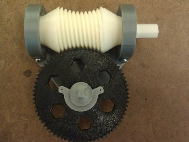
Worm gears are vital in engineering applications for their compact size and high reduction ratios, but they have a disadvantage where only one tooth on the spur gear meshes with the worm at once, causing high contact stresses that accelerate wear. However, this demonstration model displays a hyperbolic or enveloping worm gear; both the worm gear and spur gear teeth are cut from hyperbolic surfaces, allowing multiple teeth to engage simultaneously. This reduces contact stress between gears, enabling higher torques to be transmitted through the gearset. A video showcasing the motion of these hyperbolic worm gears can be viewed here: http://youtu.be/O-MFFjBNCb8. In this design, 12 teeth on the spur are theoretically in constant mesh with the worm gear, although manufacturing tolerances result in less-than-perfect contact. The gear reduction is 72:1 (72 revolutions of the worm gear produce one revolution of the spur gear). Both the worm and spur gears have true involute profiles. The worm gear is mounted horizontally on knife-edge bearings, and the spur is fastened to a vertical shaft using a c-clip. This model serves as an excellent hands-on demonstration for students of various levels while also presenting a challenge in computing and modeling worm gear geometry. Solidworks files for both the worm and spur gears have been attached for those interested. To print all components except bearing_cap, use a layer thickness of 0.2 mm for the involute and spur gears, and other parts' layer thickness is not critical. Four M3 screws are required to attach the bearing caps to the base. The worm gear requires some cleanup, trimming off a large pad for improved print bed attachment and smoothing out steep overhangs on gear teeth for smooth rotation. A 10mm socket or drill driver can be used to spin the gearset more rapidly. It is advisable to lubricate the knife-edge bearings holding the worm gear with graphite to prevent excessive friction.
With this file you will be able to print Hyperbolic Worm Gears with your 3D printer. Click on the button and save the file on your computer to work, edit or customize your design. You can also find more 3D designs for printers on Hyperbolic Worm Gears.