Hypercube Max - Lutra 3D
thingiverse
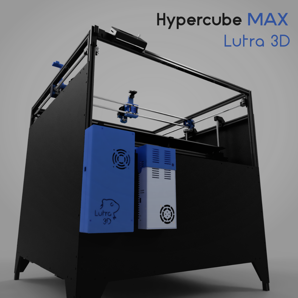
## Features - 620x600x550 mm build volume - Sensorless homing - Exchangeable hotend compatible with Hypercube Evolution - Automatic bed leveling I wanted to scale the Hypercube evolution printer to be able to print 600x600x500 mm build volume. As it turns out, doubling the dimensions takes much more than just buying longer frame extrusions and guiding rods. ## Construction - For offsets of the Z Axis parts please see the included pictures with dimensions. - See the detail picture for the print bed corner assembly with bearings - See the detail picture for upper leadscrew bearing assembly - See the detail picture for lower leadscrew bearing and Z axis motor assembly - To help you with aligning the Z-Carrige parts please use attached aligment sticks. They are marked with their length in milimeters ## Material list Thank you for checking out my printer, I was surprised, how many parts it takes to assemble it. It is possible that I made a mistake somewhere or had forgotten an important part. If something does not look right, please let me know. - For a more structured **Material list**, see also **datasheet** in **CSV** format included among thing files ### Fasteners These are generally used to fasten parts to the main frame and the print bed frame. - (approx.) 100 x 8 mm **M5SH6 M5 Stainless Steel Hex Socket Button Head Screw Bolt** - (approx) 150 x 10 mm **M5SH6 M5 Stainless Steel Hex Socket Button Head Screw Bolt** - (approx.) 100 x 12 mm **M5SH6 M5 Stainless Steel Hex Socket Button Head Screw Bolt** - (approx.) 200 x **M5 T Sliding Nut Zinc Plated** These are generally used in tandem with the brass inserts to fasten the printed parts together. - M3SS2 M3 442Pcs Stainless Steel Allen Bolt Nut Hex Socket Cap Screw Assortment Kit - It is more practical to buy the whole kit the to source specific lengths individually Bras inserts are used where plastic part needs to receive a threaded fastener. I used to use the cheap inserts from Banggood, but those pull out easily as they are designed for injection molded and not 3D printed parts. Therefore I started using the Ruthex brass inserts specifically made for 3D printing, and they are great. - (approx.) 200 x **Ruthex RX-M3x5.7 threaded inserts** - All my 3D printed parts are designed to use these. ### Frame - 4 x 900 mm **2020 T-slot Aluminum Extrusions** - for the main frame legs - 11 x 800 mm **2020 T-slot Aluminum Extrusions** - for the main frame and the print bed frame - 4 x 500 mm **2020 T-slot Aluminum Extrusions** - for the print bed frame - 14 x **2020 Aluminium Angle Corner Joint** - for the main frame - 34 x **L Shape Inner Corner Joint Bracket for 2020** - 22 for the main frame and 12 for the print bed frame ### XY System **Rods:** As far as the rail rods go, it is crucial to ensure they are straight, ground to good precision (H6 or better), and hardened. If the precision is not good enough, the ball bearings will be too loose at some places while too tight elsewhere. As a result, the same force moves the bearings at a different rate, and the prints are uneven. If the rods are not hardened, the bearings will grind grooves into the rod, and the bearings will be binding. This is why using any stretched/extruded rods is not good enough. - 2 x 800 mm **W10 - Hardened steel rods of 10 mm diameter** - For Y axis rails - 2 x 830 mm **W10 - Hardened steel rods of 10 mm diameter** - For X axis rails **Bearings:** The linear bearings have been the most frustrating part of this project, hands down. It is very hard to get good quality bearings that won't bind for a reasonable price as I am writing this. I always test my bearings by lubricating them and slowly sliding them up and down the test rod. I know the test rod is straight and of good precision. If the bearing binds or I feel uneven force along the way, I know the bearing will cause problems down the line. The bearings from China have a success rate of 1 good in 5 tested. What's worse, my local suppliers tend to sell those subpar bearings from china for an inflated price. I am currently looking for a reliable source of linear bearings. - 4 x **LM10UU bearing** - for the X carriage - 2 x **LM10LUU bearing** - for the two Y carriages **Pulleys:** - 6 x **20T GT2 Aluminum Timing Pulley with teeth** - for XY idlers and the Y axis carriage - 2 x **20T GT2 Aluminum Timing Pulley without teeth** - for the Y axis carriage - 2 x **20T GT2 Aluminum Timing Pulley, 5 mm bore** - for the XY stepper motors - 4 x **M3 round spacers** - for spacing out XY idler pulleys - 1 x **10M GT2 6mm wide open timing belt** - To connect the XY System **Motors:** - 2 x **NEMA 17 40mm** **Other:** - 4 x **Steel pins, 12 mm long 3 mm diameter** - to help anchor the extruder to the X carriage - 2 x **Cable carrier chain 20x10 mm R28, 1 meter with end terminals** - check that the end terminal holes match up ### Z motion system I was forced to redesign the original Hypercube Evolution Z motion system quite a bit. At 600x700mm mirror on top, the print-bed was too heavy for standard 8 mm 3D printer lead screws, plus the stepper motors needed to be geared down to give them a bit more power. Due to the bed size, it is much harder to keep it level. As a solution, I connected each Z motor to its own stepper driver. This way, I can use "Z Steppers Auto-Alignment" function in Marlin to level the bed. Arguably even at this size 1 stepper motor per print-bed corner would be beneficial. **Rods:** - 4 x 700 mm **W12 Hardened steel rods of 12 mm diameter** - for the Z axis rails - 2 x 750 mm **TR 1203 Trapezoidal lead screw of 12mm diameter ad 3 mm pitch** **Bearings:** - 4 x **KP001 - 12mm bearing** - these hold the lead screws - 8 x **M5 25 mm stainless steel bolt, Hex Socket Cap** - to fasten the bearings to the bearing holders - 4 x **M5 locking nut** - to fasten the top bearings to their respective bearing holder part **Pulleys:** - 2 x **20T GT2 Aluminum Timing Pulley, 5 mm bore** - for the Z stepper motors - 2 x **36T GT2 Aluminum Timing Pulley, 12 mm bore** - for the Z axis leadscrews - 2 x **200 mm GT2 closed timing belt** - to transfer power from the stepper motor to the leadscrew **Motors:** - 2 x **NEMA 17 40mm** ### Print bed - 1 x **700x600 mm mirror** - to print on - 2 x **TRM-BR 1203** - Cylindrical brass trapezoidal nut, 12mm inner diameter, 3mm pitch 22 mm outer diameter 20 mm length - a fitting nut for the Z axis leadscrew **Bearings:** - 8 x **LM12UU linear bearing** - to slide on the Z axis rails ### Electronics **Power supply** - 1 x **Switching Power Supply 220V To 24V 20A 480W For LED Strip Light** - but I would advise against this power supply, the quality is not great, the fan is very loud, and it's way too powerful since I don't have a heated bed anyway. - 1 x **220V, 5A power outlet socket, and 6A fuse** - Not the best, probably will change for something better **Control boards** - 1 x **BIGTREETECH SKR Pro V1.1 Control Board** - 2 x **BIGTREETECH TMC2209 V1.2** - drivers for the XY stepper motors, with sensorless homing support. This enables me to get rid of optical homing sensors and detect crashes. - 3 x **BIGTREETECH TMC2208 V3.0** - drivers for the two Z axis stepper motors and the extruder. Z axes homes using a BL-Touch sensor, and the extruder does not need any crash detection. - 1 x **BIGTREETECH Mini12864 LCD** - minimalistic graphical display, gets the job done, and has a nice illumination. ### Cables and connections **Plugs for connecting extruder** I use Molex MicroFit connectors to connect extruder cable infrastructure to extruder electronics. On a printer of this size, it is beneficial to have an extruder unit that can be easily disconnected from the printer for repairs/maintenance. This is why all the extruder electronics are crimped with MicroFit Plug connectors, and all control boards to extruder cables are crimped with MicroFit Receptacle connectors on the extruder facing the end. I got MicroFit 3.0 connectors from my local electronics store. You will have to find a supplier near your location. For the hotend connection, I used a 12A locking connector, but I cannot find an international supplier for these. - 3 x **Molex MicroFit 3.0 Plug 1x2** - https://www.molex.com/molex/products/part-detail/crimp_housings/0436400201 - 3 x **Molex MicroFit 3.0 Receptacle 1x2** - https://www.molex.com/molex/products/part-detail/crimp_housings/0436450200 - 1 x **Molex MicroFit 3.0 Plug 1x3** - https://www.molex.com/molex/products/part-detail/crimp_housings/0436400311 - 1 x **Molex MicroFit 3.0 Receptacle 1x3** - https://www.molex.com/molex/products/part-detail/crimp_housings/0436450300 - 1 x **Molex MicroFit 3.0 Plug 2x2** - https://www.molex.com/molex/products/part-detail/crimp_housings/0430200400 - 1 x **Molex MicroFit 3.0 Receptacle 2x2** - https://www.molex.com/molex/products/part-detail/crimp_housings/0430250400 **Cable terminals for connecting extruder** Female terminals go into the plug housing Male terminals go into the receptacle housing - 50 x **MicroFit 3.0 Crimp Terminal, Female** - https://www.molex.com/molex/products/part-detail/crimp_terminals/0430300002 - 50 x **MicroFit 3.0 Crimp Terminal, Male** - https://www.molex.com/molex/products/part-detail/crimp_terminals/0430310002 **Plugs for connecting to the control board** Braintreetech SKR PRO board uses 2.54mm Pitch Receptacles. This makes our job easier. The only real challenge is connecting BL-Touch since it uses only naked pins, and on top of that, the board has 4 pins for BL-Touch instead of standard 5, so you have to sacrifice one ground connection. - 1 x **2.54mm Pitch Terminal Kit** - https://www.aliexpress.com/item/230pcs-XH2-54-2p-3p-4p-5-pin-2-54mm-Pitch-Terminal-Kit-Housing-Pin-Header/32760531736.html?spm=a2g0s.9042311.0.0.38364c4dMOLmPc - 1 x **4p Dupont connector** - for connecting BL-Touch **Stepper motor plugs** - 5 x **6pin PH2.0 connectors** - I bought a kit, https://www.aliexpress.com/item/32965581442.html?spm=a2g0s.9042311.0.0.38364c4dMOLmPc ### Cables I simply use the 20pin 5M rolls, and I cut them to match the length and number of pins as needed. - 1 x **AWG18 gauge wire, 2pin** - For the extruder heating element connection - 1 x **AWG22 gauge wire 20pin 5M roll** - for connecting the 5 stepper motors - 2 x **AWG24 gauge wire 20pin 5M roll** - for connecting the cooling fans, BL-Touch, thermistor, filament runout sensor, and everything other that runs on low current. ### Extruder I was trying to design my own extruder, but then I tried E3D Hemera, and it was just so much better than anything I had tried before, so I stayed with it. - 1 x **E3D Hemera Direct Kit, 1.75mm, 24V** - https://e3d-online.com/products/e3d-hemera-direct-kit-1-75mm - 1 x **Vulcano upgrade kit, 1.75mm, 24V** - https://e3d-online.com/products/volcano-upgrade-kit - 1 x **Creality BL Touch Autoleveling device** - for auto bed leveling - 1 x **DC24V Cooling Fan** - for part cooling ### Covers Besides looking good, the covers are important for stiffening and stabilizing the printer. Without them, the printer is susceptible to vibrations, as I decided to use quite a thin frame. I included sketches with the holes and cutouts for the bottom, front, back, and side covers. I personally dint use CNC, I just hand-drawn the lines on HDF boards from a hardware store and cut out the shapes using a vibration saw. Holes are drilled using a 6 mm wood drilling bit. The paint I used is standard water-based black acrylic paint. **Parts used from Hypercube Evolution** This printer design uses some parts from the Hypercube Evolution design. For convenience, I am including them with Hypercube MAX original parts. - 2 x **Y_Carrige_Clamp_LM10UU_1.0** - 2 x **Y_Carrige_xDia10_LM10UU_1.0** - 2 x **X_End_Stop_Flag_1.0** - 4 x **Belt_Tensioner_1.0.stl** - 2 x **Belt_Clamp_1.0**
With this file you will be able to print Hypercube Max - Lutra 3D with your 3D printer. Click on the button and save the file on your computer to work, edit or customize your design. You can also find more 3D designs for printers on Hypercube Max - Lutra 3D.