i3 Mega Light Bar Installation
thingiverse
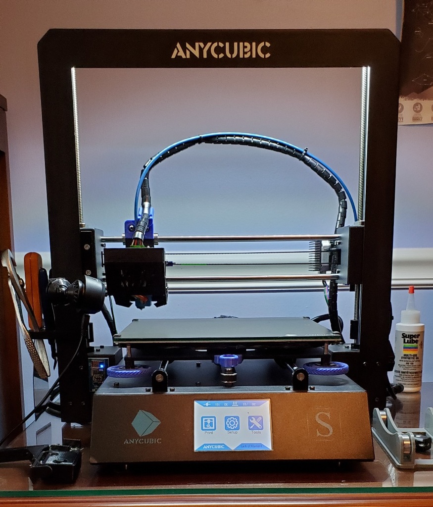
Ever wanted to actually see what you're printing? Then this tutorial is the right guide for you! Parts to print: 1. The wire guide found in the thing files on this page Parts to buy: 1. 35cm clear white LED bar (https://www.aliexpress.com/item/1005002602096095.html?spm=a2g0s.9042311.0.0.670d4c4dRXydak) 2. Buck converter, with LED display (https://www.aliexpress.com/item/32810058963.html?spm=a2g0o.productlist.0.0.2698f729KQxahn&algo_pvid=2cf478e1-90b0-4a93-92d9-2b11d4bbbf75&algo_exp_id=2cf478e1-90b0-4a93-92d9-2b11d4bbbf75-28&pdp_ext_f=%7B%22sku_id%22%3A%2264475515938%22%7D) 3. 40cm dupont cable with at least one female connector (https://www.aliexpress.com/item/4000203371860.html?spm=a2g0o.productlist.0.0.58d2125bGEfun6&algo_pvid=dec51780-004a-4186-b195-bb5e7f2ed2af&algo_exp_id=dec51780-004a-4186-b195-bb5e7f2ed2af-0&pdp_ext_f=%7B%22sku_id%22%3A%2210000000774493026%22%7D) 4. Double-sided adhesive pads, at least 50x50mm (https://www.aliexpress.com/item/1005002901916732.html?spm=a2g0o.productlist.0.0.61dd764feQBbIq&algo_pvid=2aabb276-a83f-4df5-ade5-8ec89386877a&algo_exp_id=2aabb276-a83f-4df5-ade5-8ec89386877a-0&pdp_ext_f=%7B%22sku_id%22%3A%2212000022691478455%22%7D) Note: there are many versions of the LED buck converter. The one I linked is great because it has a button that turns off the display when you don't need it on, which is nice. But other versions will work too. Instructions: 1. Cut the cord on the light bar above the switch and slide wire into the printed wire guide. Shorten and solder the wire to the correct length (see pictures). 2. Use the adhesive pads to secure the light bar to the printer frame, and hot glue the switch the the frame. 3. Cut off the usb plug on the end of the led cable, and route the cable through the hole for the z axis limit switch (see pictures). 4. Remove printer bottom cover, route led cable through space between breakout board printer frame. 5. Solder end of dupont cable to buck converter (or attach via screw terminals, but soldering is more secure). 6. Connect femal end of dupont cable to 12v and GND pins on motherboard (see pictures). 7. Power on printer and adjust buck converter to bring voltage down to 5v. The power coming into the buck converter should be more than 12v, mine was around 12.9v. 8. Power off printer, connect led cable to output of buck converter. 9. Secure buck converter to printer frame with adhesive pads. Make sure to not press down too hard because the pins on the back of the buck converter could cut through the pads and make contact with the metal frame, which could cause a short circuit. 10. Reinstall bottom cover, power on and enjoy! Note: there are also a couple of 5v pins on the printer motherboard. I have not tried these and do not know if they are a better alternative to the buck converter. At least with the buck converter you can be sure the voltage going to the light is exactly 5v. Also, if anyone knows if that 12v pin can be controlled via software, let me know! If you have any questions feel free to ask!
With this file you will be able to print i3 Mega Light Bar Installation with your 3D printer. Click on the button and save the file on your computer to work, edit or customize your design. You can also find more 3D designs for printers on i3 Mega Light Bar Installation.