i3 PINDA Probe Eliminator Project
thingiverse
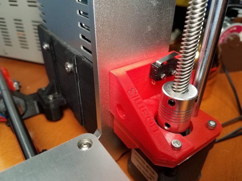
### The PINDA probe on my machine is un-reliable since during the course of many prints my left and right steppers become mis-aligned requiring me to move both sides to the top until they collide with the upper bracket. Also I would like to start using non-metallic surfaces. ### AnyCubic i3 Mega style printers got it right with its 2 limit switches on each side and individually controlled z axis stepper motors. In this configuration bed leveling is pretty much set and forget. ### This project consists of the left and right size z-limit switch mount for the Prusa i3 MK2, MK3, clones. ### This thing is part of a bigger project, Github page: [https://github.com/numberformat/noami3](https://github.com/numberformat/noami3) the project aims to make it easier for anyone to build an i3 compatible clone from parts commonly available. ### Requirements - Prusa Clone using Arduino Mega on a RAMPS 1.4 or similar board. - Printed Z limit switch holders left and right - 10T85 limit switches and wires - Download of Marlin firmware from github - Existing Marlin configuration for your printer - Arduino IDE - Extra Stepper driver or similar https://www.pololu.com/product/1182 ### Install the endstop holder and switch - Right and left switch wire length is 26, and 12 inches - Attach the left limit switch to the Z- and the right to Z+ - There are 3 pins for the end stop connector and only 2 wires coming from the switch so be mindful of the polarity hooking end stop the wrong way can smoke your main board. ### Firmware 1.0.x First update the firmware by editing the following files. This is on top of your existing Marlin configuration. If you don't have the original configuration files used then you will need to configure your printer from scratch. At a minimum you will need to re-calibrate your printer since important setting are stored in your firmware like steps / mm for each axis. So its good to keep your configurations file around. ### If your are using Marlin v1 Configuration.h Uncomment the following in Endstop Settings ```c #define USE_ZMAX_PLUG ``` Configuration_adv.h ```c #define Z_DUAL_STEPPER_DRIVERS // NV: Enabled #if ENABLED(Z_DUAL_STEPPER_DRIVERS) #define Z_DUAL_ENDSTOPS #if ENABLED(Z_DUAL_ENDSTOPS) #define Z2_USE_ENDSTOP _ZMAX_ // NV: updated to ZMax #define Z_DUAL_ENDSTOPS_ADJUSTMENT 0 #endif #endif ``` ### If you are using Marlin v2 ```patch // // For Z set the number of stepper drivers // -#define NUM_Z_STEPPER_DRIVERS 1 // (1-4) Z options change based on how many +#define NUM_Z_STEPPER_DRIVERS 2 // (1-4) Z options change based on how many #if NUM_Z_STEPPER_DRIVERS > 1 - //#define Z_MULTI_ENDSTOPS + #define Z_MULTI_ENDSTOPS #if ENABLED(Z_MULTI_ENDSTOPS) - #define Z2_USE_ENDSTOP _XMAX_ + #define Z2_USE_ENDSTOP _ZMAX_ #define Z2_ENDSTOP_ADJUSTMENT 0 #if NUM_Z_STEPPER_DRIVERS >= 3 #define Z3_USE_ENDSTOP _YMAX_ ``` ### Upload Firmware steps - Hook up your printer via USB to the computer upload the firmware - Download and open Pronterface - Select the com port and connect to the printer. - Test the status of your endstops by issuing a M119 in pronterface. The output should look something like this. ``` SENDING:M119 Reporting endstop status x_min: open y_min: open z_min: open z2_min: TRIGGERED ``` ### Stepper Driver Install - Power down and unplug printer - Install the extra stepper driver into the second extruder spot - Connect the right side z stepper motor to the second extruder output ### Final Testing With your Z axis lead screws removed you can test your x axis steppers. - Leave the 2 lead screws on the Z axis disconnected - Using Pronterface - Home the X axis and manually trip the x axis limit switch - Home the Z axis - both steppers should rotate ( make sure to verify correct direction) - click and hold the right end-stop and the right stepper should stop - click and hold the left end-stop and verify the left stepper stops ## Tips on using manual bed leveling Note for i3 MK2 style printers: Each time you move your printer to a new location you would need to perform bed leveling again. This is because the i3 MK2 style printers have a base made primary threaded rods which flex pretty easy. If placed on an un-even table If the base flexes just a small amount it will affect your nozzle clearance. But thankfully this is a one type operation with each move.
With this file you will be able to print i3 PINDA Probe Eliminator Project with your 3D printer. Click on the button and save the file on your computer to work, edit or customize your design. You can also find more 3D designs for printers on i3 PINDA Probe Eliminator Project.