Image to Textured Anulus (Ring) Python Tool
thingiverse
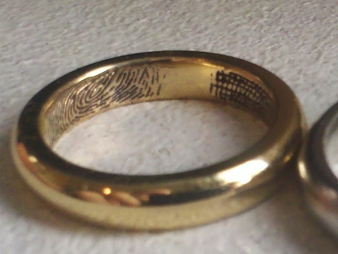
Originally, this script converted images into height maps suitable for use in OpenSCAD as polyhedrons. It now transforms images into textured ring shapes. Adding control to fade edge pixels is still a task, and sizes in the .STL file may differ from entered values. The tool now generates non-textured rings with correct dimensions, but adding an embossed texture inside increases material. Fixed issues include adjusting texture depth, changing ring width, including engraving text, and altering the ratio of texture height to ring circumference. Doming has improved, and a new version is v0-12. Further improvements include controlling the amount of pattern coverage, adding texture_scale ability, and fixing possible bugs with texture direction when using partial coverage. The tool can now create complete rings, invert/flip/rotate images, control emboss/engrave options, and implement curving in a second direction. Output is now available in ASCII .STL format, and the script has undergone significant cleanup. It requires Python 2.X with PIL, PyLab, NumPy, and a greyscale height-mapped image for input. Be prepared for large output files that may take time to generate and open.
With this file you will be able to print Image to Textured Anulus (Ring) Python Tool with your 3D printer. Click on the button and save the file on your computer to work, edit or customize your design. You can also find more 3D designs for printers on Image to Textured Anulus (Ring) Python Tool.