Improved Duet3d Indirect Laser Filament Sensor
thingiverse
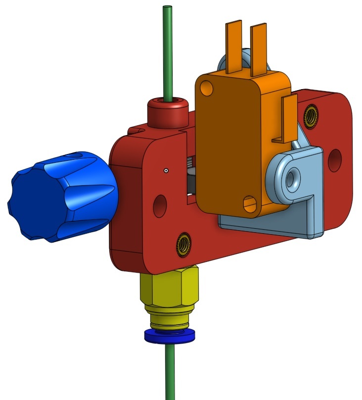
I love the original carbon fiber indirect laser filament sensor. I built the original and had some issues with the idler assembly. I also very much desired to have the static filament sensor switch capability so my system would be aware of the filament presence status to manage macros and scripts. I saw this as an opportunity to kill two birds with one stone. I replaced the idler assembly with a short lever arm micro switch to act as both the idler assembly and a presence switch. Added Features: * Knob to make loading and unloading easier and to help the viewer see if the sensor is registering movement * Added a common pneumatic connector on the output side * Added a micro switch for the idler assembly and connected it to the switch inputs on the duet board. The micro switch can be fine tuned by a set screw for sensitivity * Changed the hob to a black Mk3 style for better friction and registration which required housing resizing * Included a simple bracket for my Ender/Hemera configuration (optional) * Added a dual light fiber window (top and bottom) to see the data state of the sensor * Added brass nuts in common areas * Added the connector hole for the switch connector on the Duet board The Hemera bracket is intended to be used on an Ender 5 that has been modified to be used with a Hemera direct drive extruder. This bracket is optional. Materials ======= * Dual pin header to leverage the micro switch with the Duet3D laser monitor https://amzn.to/2F28p4k * Microswitch https://amzn.to/31XOMU5 * Bowden Tubing https://amzn.to/3hXAPLm * PFTE Connector https://amzn.to/354q5qS * Brass Nuts M3 x 4mm (L) x 5.3mm (OD) https://amzn.to/2EZrfcm * Duet3d Laser Sensor Monitor or clone (v2) Board (Numerous Sources) * (2) M2 x 6mm Screws - Fasten board to enclosure * (1) M2 x 5mm Screw - Knob retention (optional) https://amzn.to/31TdLYq * (2) M3 x 20mm Hex Socket Cap Bolts - Mate enclosure together * (1) M3 x 12mm Hex Socket Cap Bolts - Mate switch bracket to the enclosure * (1) M3 x 8mm Hex Socket Cap Bolts - For micro switch tuning screw * (1) M3 x 12mm Hex Socket Cap Bolt - Mate/pivot for switch to the switch bracket https://amzn.to/32VThOc * (2) Bearings 5x9x3mm https://amzn.to/3jN7vYz * (1) Carbon fiber rod 5mm Bore with 75mm Length https://amzn.to/353QDIE * Clear Filament (1.75mm) for LED light tube https://amzn.to/32YMVxD * Wire leads to connect Duet board to the switch https://amzn.to/3lHa7c2 * MK3 Hob https://amzn.to/3lPDo4f Example performance: <pre><code>9/12/2020, 9:03:10 PM M591 D0 Duet3D laser filament monitor v2 with switch on pin e0stop, enabled, allow 200% to 260%, check every 3.0mm, version 2, quality 221, brightness 255, shutter 84, measured min 225% avg 240% max 257% over 13515.3mm</code></pre> The Hemera bracket is intended to be used on an Ender 5 that has been modified to be used with a Hemera direct drive extruder. This bracket is optional. Tools ==== * Soldering Iron * Allen Wrench (M3) * Super Glue * hacksaw or carpet knife Assembly ======== * Print the top, bottom, switch bracket and optional hemera bracket * Solder the two pin header to the back of the Duet3d PCB board * Fasten the PCB to the enclosure with two M2x6mm screws * Cut the carbon tube to 7mm in length using a hacksaw in a vise or carpet knife and then press the knob onto the end and optionally tighten the knob in place with a M2x5 screw * insert the clear filament into the filament light guide holes. This will filament will pass over the top of the status LED on the board and exit the enclosure on both sides. * attach the M3 hob to the carbon rod with bearings at each end. * Put a dab of super glue on the carbon rods to help hold the bearings in place * align the M3 hob with the filament feed path and fasten down the set screw to hold it in place * press in the four brass nuts. Two on the ears of the enclosure and the remaining two on in the enclosure mate holes as pictured * using pliers thread the PTFE connector onto the exit side of the enclosure * press 3" section of bowden tube into the feed side. You may need to tweak the size for fit. * using dual female pin connector. Attach it to the back of the enclosure and solder it to the Common and Normally Open connectors of the switch (see images) Update the config.g file RRF 3.2x: <code>M591 D0 P6 C"e0stop" R90:110 E3.0 L0.418 S1</code> The L is the configuration factor. You can tweak this value until your average is close to 100% Note: The S0 parameter disables the sensor by default. Once you are confident in the configuration change this parameter to S1 Note_2: In firmware 3.2 and later the L parameter can be used to accommodate for the difference between the 5mm bore and the M3 hob. This parameter can be used to normalize the reporting to between 0-100% Lnn (firmware 3.2 and later) Calibration factor, default 1.0. The filament movement reported by the laser sensor is multiplied by this value before being compared with the commanded extrusion. Intended for use with sensors that use the laser to read movement of a wheel that is turned by the filament.
With this file you will be able to print Improved Duet3d Indirect Laser Filament Sensor with your 3D printer. Click on the button and save the file on your computer to work, edit or customize your design. You can also find more 3D designs for printers on Improved Duet3d Indirect Laser Filament Sensor.