Inductive Probe Edition
thingiverse
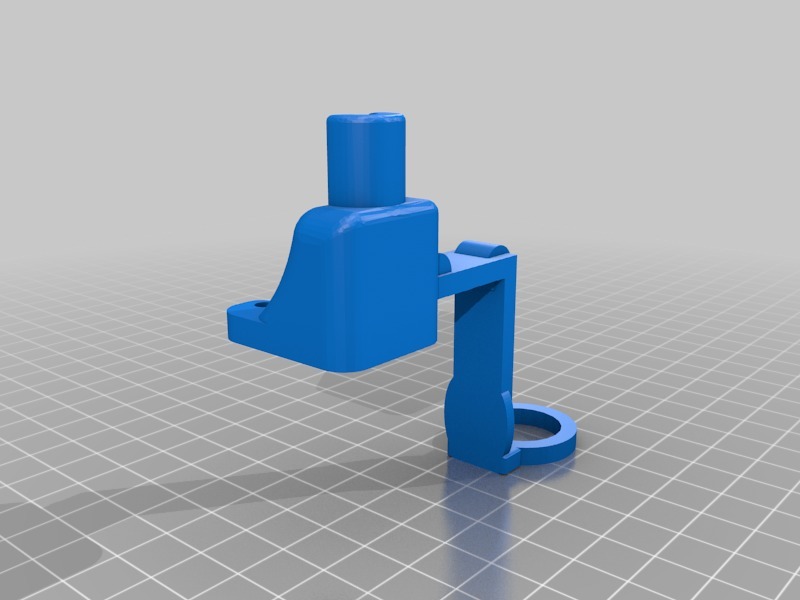
**update*** accidentally uploaded the prototype mount... correct ABL mount uploaded. This thing is a work in progress... Per the usual, I take no responsibility for starting fires and killing electronics. First and foremost... this was made possible by many, many resources online,,, I simply adapted them for use on the Gen L board. This guy is a legend: https://mertarauh.com/ (very good read). Add an Inductive sensor/probe to the JGAurora A5. This is the prototype... it's fully functional but can use some improvement. Step 1, the build surface: You need to make a flexible/removable print surface. Buy a 12 by 24 thin sheet of cold rolled steel at a big box home improvement. Cut it in half with shears (makes 2). Cover each with your build surface of choice. I used PEI on one, and blue tape on the other. example== https://www.lowes.com/pd/Hillman-12-in-x-2-ft-Cold-Rolled-Weldable-Steel-Sheet-Metal/3050447 this gives you flexibility for different materials. ***you can clamp these on or use magnets... your choice.*** I use mine directly over the diamond print surface. Step 2, The probe: Install the probe mount, drop in the inductive probe, and upload the firmware. unplug the old endstop, and wire up your inductive probe. See pictures for wiring. Step 3, Making it work: Raise your Z up a bit... give yourself plenty of room and carefully test your probe operation... be prepared to kill the power if the probe wont stop the z travel while testing.. All is working if the probe is triggering (LED light up), and the z travel stops as advertised when the probe is near metal (I used an old set of plyers but any metal object will do). Now, use the touchscreen to slowly lower your nozzle to the build surface... a thick paper or business card is the correct distance. adjust your probe in the mount to trigger at that height, and tighten it down. Step 4: The Z offset.... Any z adjustments will occur in the starting Gcode of your slicer. you will need to dial this in. Here is my starting gcode for example.... G28 ; Home all axis G29 ; Level the bed surface (auto bed level) G92 E0 ; Reset extruder length to zero G1 F200 E1 ; Extrude 1mm at 200mm/min G92 E0 ; Reset extruder length to zero M206 Z 1.5 ; Set Z offset to 1.5mm above print surface - further + closer BOM: = Inductive probe NPN NO {LJ18A3-8-Z/BZ} or similar. NPN NO gets around the MKS Gen L internal pullup resister. https://www.aliexpress.com/item/3-Wire-LJ18A3-8-Z-BX-8mm-LW-Approach-Inductive-Proximity-Sensor-NPN-NO-Switch-DC/32843128116.html?spm=2114.search0204.3.9.720a2939cVxu7k&ws_ab_test=searchweb0_0,searchweb201602_3_10065_10068_10130_10890_10547_319_10546_317_10548_10545_10696_453_10084_454_10083_10618_431_10307_537_536_10059_10884_10887_100031_321_322_10103,searchweb201603_53,ppcSwitch_0_ppcChannel&algo_expid=8862c651-6e82-41e1-a37e-d7a4f6caed0f-1&algo_pvid=8862c651-6e82-41e1-a37e-d7a4f6caed0f&transAbTest=ae803_5 = Diode 1N5338B is what I used, but according to the internet 1N4148 will also work https://www.microcenter.com/product/392683/1n5338b-51v-5-watt-zener-diode---5-pack = 3 pin connector {male} to build your plug. (save your original plug in case you ever want to go back). I used an old servo cable had from a drone... https://www.ebay.com/itm/New-RC-Servo-Extension-Cord-Lead-Wire-Receiver-Cable-Male-Female-Connectors/112959837197?epid=2220178249&hash=item1a4cee540d:m:m7iwnYH5MBQVoFJUMtsMiow:rk:4:pf:1&frcectupt=true
With this file you will be able to print Inductive Probe Edition with your 3D printer. Click on the button and save the file on your computer to work, edit or customize your design. You can also find more 3D designs for printers on Inductive Probe Edition.