Inexpensive Colorimeter
thingiverse
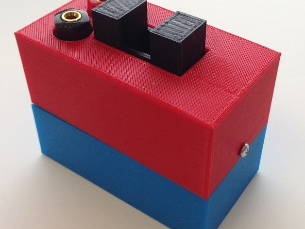
This is a colorimeter that relies on LEDs for both the light source and measurement. Assembly Instructions Below is a detailed description of the assembly of a colorimeter suitable for use in an introductory chemistry course. Using plastic pieces made with a 3D printer along with some minimal wiring supplies, it is possible to construct this device for around five dollars. This guide is designed to allow anyone with access to a 3D printer to make a colorimeter, and to that end assumes only a very limited knowledge of 3D printing as well as very basic wiring skills. No soldering is necessary and the only tool needed is a screwdriver. Materials: • Plastic housing – 3 pieces • AA battery case with on/off switch • 2 AA batteries • 400 ohm resister • 5 screws (#4 x 3/8 inch pan Phillips for metal) • Banana socket • Electrical Tape • 3 small wire nuts • 5mm LED • 10mm red LED • Voltmeter The files required for printing the plastic portions are Mendez – Colorimeter-Top.stl, Mendez –Colorimeter - Center.stl, and Mendez – Colorimeter - Bottom.stl. The colorimeter described here was printed on a Makerbot Mini with standard settings (2 shells, 20% infill and 0.2mm layer height). Circuit The operation of this device is based on two circuits. In the first, two batteries are used to power a source LED. The light from this LED induced a voltage change in the detector LED that is measured by a voltmeter. Assembly Step 1 - Begin assembly by placing the battery case into the bottom casing, making sure to line up the switch on the bottom with the opening on the casing. The wiring should stick up near the corner without any screw holes. Step 2 - Thread the wiring from the battery case through the large hole in the middle casing piece. The middle casing piece should sit on the inner ledge of the bottom casing with the three screw holes lining up. Carefully screw in the three screws. None of the holes in either the middle or bottom casings are threaded, so some force may be required to start the screws. Be careful not to create new holes while screwing, which could disrupt the alignment of the other screws. Step 3 – Insert the source LED in the smaller hole in the middle casing. Applying some pressure with your thumb may be necessary but it should snap into place. Spread the wires apart and use electrical tape to ensure they stay apart. Make sure that both wires are unobstructed and still accessible for later steps. Step 4 - Using the wire connectors, connect the red wire to the negative terminal of the LED (the short one). Next connect the resister to the black wire and then to the positive terminal of the LED. Do not turn on the battery without a resistor connected; this could burn out the LED. Step 5 - Now is a good time to test the system. Turn on the battery case and look for a light. Remember, LEDs are not multi-directional; if the wiring is switched, it will not work. Assemble the detector apparatus by attaching the 10mm LED to the banana socket. The short lead of the LED should be connected to the red, while the long lead should connect to the black. Step 6 - Insert the 10mm LED into the larger opening on the middle casing piece. Like the source LED, it should snap into place but may require applying pressure. Use electrical tape to ensure it stays in place while you place the cover on in the next step. Step 7 - Carefully place the top casing piece on top, lining up the openings for the cuvette and banana socket. You may need to slightly adjust the angle of the banana socket but once the cover is on, the banana socket should be stable. There is plenty of room for the wiring, but you may need to move the source LED wiring so that it does not stick out the sides. Secure the top to the middle with two screws, being careful to line up the holes. Step 8 - Once the case is on, connect it to a multimeter and test the device. If everything is working, you should read a voltage around 1V with a blank cuvette in the holder. Additional Considerations: • While any 5mm LED in the visible spectrum should work, the resistor and battery described above are tuned for conventional 5mm red and green LEDs. Other LEDs may turn on but may not be bright enough to register on the detector. • The intensity of the light and the range of source LEDs can be modified by adding or removing resistors or changing the voltage of the batteries. • A 10mm cuvette can hold around 3ml of liquid, but because the LEDs are so low in the device, only 1ml is actually required. • While the top of the cuvette remains open, this was found to have no noticeable effect on the resulting absorbance data. • If the voltage reading on the multimeter is negative, then you probably switched the wiring on the detector. This is fine for the detector, but the source LED will not turn on if wired incorrectly.
With this file you will be able to print Inexpensive Colorimeter with your 3D printer. Click on the button and save the file on your computer to work, edit or customize your design. You can also find more 3D designs for printers on Inexpensive Colorimeter.