INLretro basic chipset enclosure PCB v2.0
thingiverse
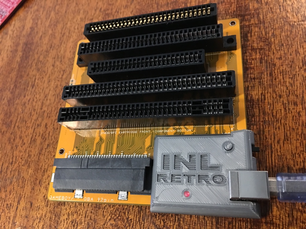
Simple chipset enclosure for INLretro programmer dumper PCB v2.0 (APR2018 dated on PCB) Later PCB versions change the reset and Bootload switch design. Screw holes are for 2.6mm coarse threaded screws up to ~5mm long. LIght pipe isn't really necessary, but helps see dim LED from an angle. When the LED is fully lit it's clearly visible from any angle without a light pipe. Debug header version has cutout for ARM serial wire debugger, that header isn't present on purchased devices as it's only useful for advanced firmware development. Bootloader switch can be used for updating mcu firmware over USB after all. But if you soldered your own debug header on the board, then you'll want to print that version. Set of light pipes in varying sizes as the number of perimeters can greatly affect final sizing. I think the light pipes turn out best with 3 perimeters which ends up giving 100% infill on the upper/narrow end on my Prusa MK2S with normal 0.2mm layer height. 2 different reset button options depending if want raised or near flush. Created with tinkercad, design is open for modification: https://www.tinkercad.com/things/doy0nrnXexX
With this file you will be able to print INLretro basic chipset enclosure PCB v2.0 with your 3D printer. Click on the button and save the file on your computer to work, edit or customize your design. You can also find more 3D designs for printers on INLretro basic chipset enclosure PCB v2.0.