InMoov Two Servo Linear Drive Neck
thingiverse
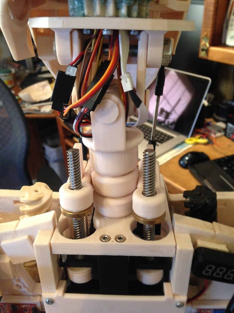
Human: Here is a video of the linear drive cube: https://youtu.be/R3sCj6oPCtw Here is a video of the Linear Drive InMoov neck installed and testing: https://youtu.be/R95s6OxsMGg I started with Gael Langevin's original InMoov neck design at www.Inmoov.fr, which only had flexion/extension and left/right rotation. I then changed to Bob Houston's articulated neck here: https://www.thingiverse.com/thing:861146 After a series of mods and patches, I decided on Drupp's Parloma style neck here: https://www.thingiverse.com/thing:2059967 Still not satisfied with the movement control, I designed a linear drive similar to my previous creation (https://www.thingiverse.com/thing:3743426) as a mod to Bob Houston's Articulating Stomach here: https://www.thingiverse.com/thing:1409964 The Drupp files are necessary for making modifications to the InMoov torso so it can receive the linear drive cube. Drupp's Parloma Neck fits in this same space. HomPlateBackLeft and Right needed a wee bit of trimming after install to maintain the 80mm width of the rear entry. Printing & Assembly Hints: Imagine these parts in a stack: Drupp_Neck_Hinge - the head mounts on this. Neck_U_Joint_Base is secured above with a 5/16" or 8mm bolt. Neck_U_Joint_Coupling assembles to the Base use the Neck_U_Joint_Star and print four Neck_U_Joint_Pins Neck_Coupling - Print two and glue and press fit them together Then glue that to the Neck_U_Joint_Coupling Neck_Servo_Lid receives the entire neck & head assembly above. Glue it in place Route all the cranial nerves into the pot frame. I used a dental mirror to get eyes on the slot for the pot in each gear. I would rotate the gear as needed so when the rack gear is inserted into the pot frame, all the way the slot would match the position of the pot turned all the way as if the gear had driven it there. Now the pots may be installed and their retainer clips slid into place. Now the Neck_Pot_Rack_Gears may be secured to the Neck_Lead_Screw_Drives Lastly, slip the Neck_Servo_Lid into place and secure with four M3 x 15mm machine screws. It is possible to wait to glue the head assy into place so you may test and calibrate the cube first. Once you have the cube tested and calibrated (I used an EZ-Robot ioTiny) then you can install the head to the cube, and the whole business into the Torso with two M3 x 15mm machine screws in front and two small self tapping screws to hold Neck_Cube_Rear_Lower_Clip in place which mounts on the lower back of the cube and holds it in place. To provide some added stability and a wire guard mount Neck_Rear_Cover on the bottom back of the skull. Drill a 2-3mm hole at the bottom of Neck_Rear_Cover. Fasten two 6mm x 25mm springs - one under each of the screws that hold the rear of the lid on. Fasten the other end of the springs to the little hole drilled in the bottom of Neck_Rear_Cover To connect the Neck_Lead_Screw_Drives to the Neck_U_Joint_Base I used M3 x 50mm threaded rods (https://www.amazon.com/gp/product/B01LWPOXJO/ref=ppx_yo_dt_b_asin_title_o01_s00?ie=UTF8&psc=1) attached to RC ball joints (https://www.amazon.com/gp/product/B07SSZ1T46/ref=ppx_yo_dt_b_asin_title_o05_s00?ie=UTF8&psc=1)
With this file you will be able to print InMoov Two Servo Linear Drive Neck with your 3D printer. Click on the button and save the file on your computer to work, edit or customize your design. You can also find more 3D designs for printers on InMoov Two Servo Linear Drive Neck.