Internal USB Power Delivery connector for the FT-817 / FT-818 transceiver
thingiverse
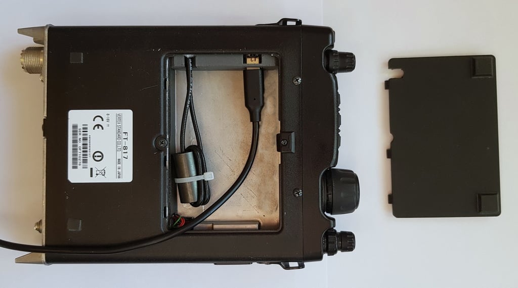
This design is for powering the FT-817 or FT-818 transceiver from a USB "Power Delivery" (PD) device such as a "power bank" battery. A USB PD connector is installed internally in the battery compartment. NOTE: The construction requires careful soldering inside the transceiver for internal connection of the power wires. Look at picture 7 and decide if you feel comfortable doing this. The design makes use of a USB PD "trigger module", a small circuit board which connects to a USB PD device and activates a desired mode, in this case a 12 volts output. The module is installed in the battery compartment of the transceiver. The 12 volt output is connected internally to the inside of the power connector. A USB cable can be routed out from a slot in the battery compartment lid. The cable may be stored in the compartment when not in use. This 3D design is simply a block to hold the trigger board in place. These boards come in a variety of sizes. The provided STL fits a common size, but your board may be different. You may be able to use the Thingiverse customizer to adapt the design, otherwise you will have to edit the values in the OpenSCAD file and generate a new STL. In brief, the assembly procedure is as follows: - Obtain a 12 volts trigger module board with a USB C connector. - Set proper variable values according to the dimensions of the board. - Print the holder block. - If desired, obtain noise damping ferrites which fit in the compartment. - Remove the top and bottom covers of the transceiver enclosure. - If desired, connect a 10-100 nF capacitor across the module output. - Use suitable power cable at most about 3 mm in diameter, 60 cm long. It is suggested to use RG-174 coax to minimize the risk of interference. - Test the function of the module by measuring voltage at the cable end. - With no USB connection, connect 12 volts to the module output and check that the parasitic current draw is acceptable (less than 1 mA). - Solder the power cable to the top of the board, leaving the bottom flat. - Insert the module into the block so that the USB connector is accessible through the hole in the side wall. - Insert the block all the way on the right side of the compartment. It should fit snugly between layers of foam padding. - Route the wire via ferrites in the compartment if desired. - Route the wire to the top of the transceiver through the hole near the back end of the block. - CAREFULLY solder the wires to the input power connector, or to nearby traces on the circuit board. This requires some care and skill. - Cut a small piece of foam, put on top of the module to hold in place. - Replace the bottom cover of the transceiver and verify that it holds the printed block in place. Add layers of tape, or print again with reduced height, if needed to make the block fit snugly. - Replace the top cover of the transceiver. - If desired, make a slot in the edge of the battery lid so that a USB cable can exit. - If desired, mount larger rubber feet under the transceiver so that the cabinet is not riding on the USB cable. Refer to the pictures for more details. Usage notes: - To activate the USB PD supply, it may be necessary to hold the power button depressed while the USB is connected to the source. - To transmit at full power, the USB PD source must be capable of delivering 12 V 3A.
With this file you will be able to print Internal USB Power Delivery connector for the FT-817 / FT-818 transceiver with your 3D printer. Click on the button and save the file on your computer to work, edit or customize your design. You can also find more 3D designs for printers on Internal USB Power Delivery connector for the FT-817 / FT-818 transceiver.