IoT Power Strip
thingiverse
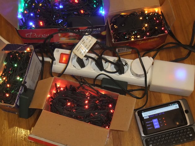
IoT Power Strip is a DIY device that allows to turn on/off two pairs of the outlet sockets via Web browser through Wi-Fi. It doesn't require any infrastructure besides the Wi-Fi enabled device with HTTP browser (e.g.: smartphone, tablet, laptop). That means that you don't need some IoT server to be installed in your intranet (like MQTT server or Web Server), you even don't have to have internet access to operate the IoT Power Strip. The example on how to use the thing for controlling two pairs of Christmas mini lights: The overview of the Web UI: Print Settings Printer Brand: RepRap Printer: Tricolor Rafts: Doesn't Matter Supports: Doesn't Matter Resolution: 0.3 mm layer height Infill: 30% except screws, 80% for screws Post-Printing Parts printed with 20% infill Parts printed with 80% infill Assembling all the parts (without modules) Assembling the box with modules How I Designed This WARNING Some parts of the DIY device described here use mains electricity. In order to build IoT Power Strip you MUST HAVE both knowledge and experience in making things with high voltage electrical parts (mains, 220V - 240V). Do it on your own risk. I will not be responsible for any loss or damage. Always check twice that the device and any of its parts/wires are NOT connected to mains before touching it! Make sure that your work-in-progress DIY project is not accessible for children, pets and others! Even if you are comfortable with working on DIY projects which involve mains electrical parts, please refresh your knowledge about electrical safety with the help of some good books/articles, for example: Keeping yourself and others safe when designing and making electronic projects Work safely with high voltage BOM You will have to have the following materials for building IoT Power Strip: Mains electric cable with plug. I have bought a cable 1.7m 3x1.5mm2 with plug for about 2$. Outlet Box with 4 sockets, switch and grounding. I had a couple of them lying around after buying a year ago in local store. The model I used called BR-1564-0. The price is up to 4.50$. ESP-01 (ESP8266 module). I have bought ESP-01 about a year ago, now you can buy a better and cheaper version, the price is 2.18$. Arduino Pro Mini. I have bought a dozen of cheap clones of it. You can buy it here for 1.75$. 2-channel Relay Module, can be bought here for 1.66$. 5V Power Supply. Again I wanted something small and easily achievable, so I have repurposed a cheap USB power supply called: "Travel Convenient EU Plug Wall USB Charger Adapter For Samsung Galaxy S5 S4 S3 Note 3 Charger 5V 2A". Of course, it will not pass even smoke test on >0.6A output current, but it work ok with 0.4A load. I have bought it here for 1.16$. LM1117-3.3 voltage regulator (or another like LD33 that can create 3.3V from 5V), two resistors for about 10k each, one electrolytical capacitor roughly 100.0 mF x 6.3V, another capacitor about 0.1 mF, a piece of solderable breadboard, 2 pieces of 1x4 2.54mm female headers (or single 2x4 2.54 female header). In total about 0.2$. 2 M3x10 countersunk screws, 1 M3X10 screw, 3 M3 nuts, 4 M3 washers, 3 M3 lock washers. I guess about 0.1$. ABS plastic, solder, rosin, low voltage wires, mains wires, a piece of kapton, narrow heatshrink. 1$ The total cost of the materials is about 15$. Tools You will have to prepare the following tools for making the thing: 3D printer; Snips; Soldering iron; Pliers; Side cuters; Tweezers; Screwdriver; Dremel or other rotary tool with a set drill and milling bits may be required; Multimeter; Goggless. How to build it The device consists of four main elements: The Electric Cable with the mains plug. The Outlet Box with four outlet sockets. You will have to hack it a little to have two groups of socket pairs. The Spacer element that adapts the curves of the Outlet Box with straightness of the Controller Box. The Controller Box stuffed with the electronic modules and wires. The fifth element is the Firmware/Software that glues everything together and makes it alive. 3D printer is used here to create/modify three of the four elements described above (2nd, 3rd, and 4th): When modifying the Outlet Box (2nd element) you will have to cut one of the mains socket bus into two pieces for conducting mains from 2-channel relay modules. The 3D-printable part mainsBreaker.stl will mechanically connect and isolate two pieces of the bus. The 3rd element is fully printed, it is used for better machanical connection between the Controller Box and the Socket Box. The 4th element is the most interesting 3D printable component. It consists of several parts designed to allocation and isolation of the following modules: ESP-01 (ESP8266) module; Arduino Pro Mini board; 2-channel Relay Module; 5V power supply; 5V->3.3V DC power convertor. I hope that the steps below will be enough for experienced makers for building the device. Disassemble the USB charger, you are interested only in board from it. Print all the components except screws using ABS with about 30% of infill (I printed it with 20% of infill but I think that higher infill level will be better). Screws shall be printed separately with about 80% of infill (also from ABS, but I would like to experiment with nylon for them). You will need 4 screws but better to print 6 of them (just in case of applying excessive force to them). Be gentle when you will be screwing them into the box, remember that they are from plastic. Try to assemble the Controller Box, it shall be simple. I have published a couple of videos how to do it: just box without modules (3D); assembling with modules (3D). In case if screws are too thick and can't fit into holes, drill the holes to be little wider. Gently hack the electric mains in the Socket Box. It should not be hard to split one of the mains buses into 2 pieces with the help of snips and allocate a printed mainsBreaker.stl among two bus pieces. The video how to do this step is here (3D). Drill 2 holes in the Outlet Box for connecting to Controller Box with M3 screws and one bigger hole between them for wires. Connect the Outlet Box (top part) with Controller Box (bottom part) with the help 2 M3 countersunk screws. Check the attached IoT-Power-Strip-schematic-diagram.png schema, it shows how modules are connected. Solder the mains part (including 5V power supply and the relay module which shall be allocated inside the bottom part of the Controller Box). Make sure that mains plug is disconnected every time you are working with the high voltage part. Check the result of soldering with the multimeter for shortcircuits and for good conducting, etc. Assemble the Outlet Box. Assemble printed powerBar.stl and relayBar.stl into bottom.stl to isolate high voltage, plug in the mains, turn on the mains and check for 5V on the power supply. Turn off the switch on the Outlet Box, disconnect the device from mains. Solder Arduino Pro Mini to the power supply and to the 2-channel Relay Module. If Arduino is pre-flashed with the default sketch, when you turn on the device you will see and hear the relay module flashing and turning on/off periodically. That means that Arduino is working. Solder 5V->3.3V module with LD33, R1 and R2 resistors and C1 and C2 capacitors (as shown on attached pictures). Connect the module to 5V and check for 3.3V. If 3.3V is ok, turn it off, plug-in ESP-01 to 5V-3.3V adapter and turn the switch on. ESP-01 shall flash once with one LED and then another LED shall be constantly shining. That points that ESP module is ok. The video with Arduino and ESP8266 connected is here (3D). Solder all the remained wires according to the schematic diagram, turn on the device and check that both ESP8266 and Arduino are working the same as before, it shall look as in this video (3D (how it will look with closed top part of the box is here (3D)). Turn off the device after checking. Flash the Arduino board through the socket in 5V->3.3V power adapter according to the README.md from the GitHub repository. Example of how Arduino is flashed shown in this video (3D). Flash the ESP8266 and upload software according to the README.md from the GitHub repository. This video (3D) shows how to flash the custom built NodeMCU version. This video (3D) shows how the software upload works when files are uploaded from batch file. Plug in ESP-01 back to 3.3V adapter, turn on the device and check with the help of any Wi-Fi device that esp-devlab-setup Wi-Fi Access Point appeared. That means that you can close the Controller Box with the printed top.stl, and screw it with 4 printed plastic screws. Now you have your IoT Power Strip assembled and ready to be used for controlling the mains outlets. Fully assembled and programmed IoT Power Strip is here (3D).
With this file you will be able to print IoT Power Strip with your 3D printer. Click on the button and save the file on your computer to work, edit or customize your design. You can also find more 3D designs for printers on IoT Power Strip.