ISS and LEO satellites tracker
cults3d
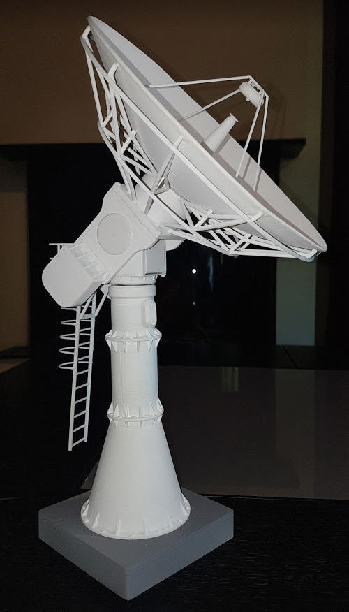
Let's start by two video of a real ISS tracking in my home :) One at 16x speed and one much longer but with explainations ! https://youtu.be/MYff_J85vZo https://youtu.be/_7pX7NHbo6A So here is a moke up of a ground station antenna, able to track any LEO sat you want. The antenna is 3D printed from a design I made starting with a 6 meter dish antenna picture. The dish is now 20cm wide, has a real paraboloid shape and is moved by two stepper motors fully hidden into the pedestal of the antenna. Two hall effect sensors and two magnets allow to setup the antenna horizontal and pointing to north at boot time. They are also hidden into the structure. An ESP32 is also hidden in the basement and is the heart of the system. It computes the position of the satellites every 1ms and computes the azimuth and elevation angles from your antenna to the satellite. An android App allows to visualize the track and to send parameters to the antenna : which satellites to follow, the Two Lines Elements and the time. https://www.b4x.com/android/forum/threads/iss-and-leo-satellites-tracker.123325/ The orbit propagator is embeded in the ESP32 and uses the excellent SGP4 library ported by hopperpop ! https://github.com/Hopperpop/Sgp4-Library the firmware was directly inspired by Alex Chang project : (Thanls Alex for sharing ) https://create.arduino.cc/projecthub/alex_chang/satellite-tracker-13a9aa How to do it : Print the dish in two halves (brim may help !). Then glue both parts with epoxy glue. Sand, fill, re sand and paint it. print the support and twelve elements of the "umbrella" Glue the dish in place and center it into its base add the horn and its supports (beware they are fragile) add also the two rings into the slots to finish the dish print the three pieces of the foot but don't glue them together now. It will be easier to glue them when te whole ntenna will be finished ! Then print the azimuth shaft parts and use a 3mm leadscrew as the shaft. see stl template for the lenght. The motors wires are slided into the roller ball bearing axis, so that they won't tangle when the antenna rotates the dish weights around 120 g. This must be balanced by counterweights on the other side of the antenna. Note that the counterweight is half the weight of the antenna dish and made with lead molten into a metal shape of the plastic counterweight. This is absolutely needed to keep the antenna balanced, as the dish weights 120g... So 60g of lead on each side, thus a total of 240g. Just small enough for the motor to be able to move all this ! don't forget to add a 2mm magnet into one of the counterweights. It will be used to calibrate the elvation motor. It mut be glue into the side which does NOT have the shape of the motor shaft. do the sae int the foot of the antenna for the azimuth axis calibration. When everything in place, glue with epoxy to seal the counterweights. Then add pieces of PLA filament to help you center the counterweights on the dish and glue all this in place. The two hall sensor and magnets must be put placed in way that the hall switch acts (closes) when the magnet is close to the sensor. If this does not happend, then simply rotates the magnet ! the motor has been modified to switch it to bipolar (to increase torque). Modification is explained here : https://www.thingiverse.com/thing:3746391 I use two "easysteppers" drivers to drive the motors. They are cheap and easy to find on ebay or aliexpress. Simple wiring, no extra jumper needed ! Please for the code refer to the excellent firmware provided by Alex Chang. I did add a lot of features and an android application to customize the antenna and see in real time the passes. May be one day, I will pusblish it !
With this file you will be able to print ISS and LEO satellites tracker with your 3D printer. Click on the button and save the file on your computer to work, edit or customize your design. You can also find more 3D designs for printers on ISS and LEO satellites tracker.