Jet Engine
thingiverse
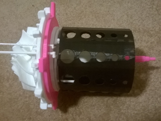
I HAVE MOVED TO GRABCAD COME JOIN ME THERE https://grabcad.com/yohann.panthakee-1 I made this.This was a challenge I set myself. I wanted to advance my Cad skills so I challenged myself to make a jet engine. Please share my design to any friends or family members who enjoy and find engineering interesting. You will need to buy:http://www.amazon.co.uk/Double-Shields-Groove-Bearings-8x22x7mm/dp/B00K85EY22/ref=pd_sim_200_7?ie=UTF8&dpID=41c8jC72QUL&dpSrc=sims&preST=_AC_UL160_SR160%2C160_&refRID=0HKD12YVC4C8MMDVSR0S Tools A set of files Sand paper By Yohann Panthakee Print Settings Printer Brand: MakerBot Printer: MakerBot Replicator (5th Generation) Supports: Yes Post-Printing How I made each part in Creo Parametric 2.0 Compressor wheel Stater part 1 Stater part 2 Stater plate Combustion chamber Gas ring part 1 Gas ring part 2 Fuel ring part 1 Fuel ring part 2 Shaft End plate Stater turbine exhaust chamber Front case How I Designed This front piece As you can see in the 3D simulation the front piece of the jet engine has a job of directing and concentrating the air flow on to the compressor wheel. This is done by the rounded edge as you can see in the 3d model.In the video you can see the air coming towards the piece and some of the air is being directed around the front case but most of the air is concentrated in the centre. You can see it better in the video below In the middle you can see a small area of light orange/red. This indicates that it is are of compression so this piece is doing its function which is to direct airflow in to the compressor wheel. compressor wheel This part is called the compressor wheel. the compressor wheel is a vital piece in the jet engine. This is because it sucks all the air from outside and compresses it to a very high pressure. In the simulation you will see that as the air comes from the front piece it will hit the compressor wheel. In the simulation you can see that the air is being twisted into a vortex. You can see it better in the video below compressor wheel This part is called the compressor wheel. the compressor wheel is a vital piece in the jet engine. this is because it sucks all the air from outside and compresses it to a very high pressure. In the simulation you can see the air hits the compressor wheel as it does this you can see that the tracers (the lines) change colour because they are changing direction because of the blades. Unfortunately I could not get the compressor wheel spinning in the simulation but if it was you would be able to see that the tracers would spin in to a vortex shape a lot more. The exhaust chamber is the final part which as much force can be produced due to the choke.This directs the air to the back propelling the jet engine forward. It also has a slight scale down for the opening. This allows for more of the air to be force out at a higher pressure and if it was real jet engine it would have more thrust. stater The stater, stater plate and nuts. The stater is designed to house the compressor wheel ,but the main feature of it is to direct the air from the compressor wheel in to a vortex motion towards the combustion chamber. This will be more efficient than just direct air flow in to the combustion chamber. combustion chamber It is also known as a burner or combustion chamber or flame holder. In the jet engine, the combustion chamber is fed high pressure air by the compression system (Compressor wheel) and is ignited at the same time creating a small explosion. The combustion then forces air out the exhaust chamber at a constant pressure. Shaft and 2 bearings Centre shaft The shaft is the centre axis where all the parts fit around. The two bearings go in to the centre of the stater and the end plate. Stater, gas ring, fuel ring, nuts (4x) The gas ring is the ignition source for the jet engine. there would be a constant flow of gas (propane) which would be lit inside of the engine. this would then instantly combustion the fuel and air mixture as soon as it came in to the combustion chamber. Stater, fuel ring, gas ring , nuts (4x) The fuel ring is where the fuel is entering in to the combustion chamber via the pipe. this the directs in to a small ring which distributes in to small streams and sprays of fuel which will then be much easier to ignite. Stater, fuel ring, gas ring , nuts (4x), front chamber The front is a piece which directs the air in to the combustion chamber. This only helps get more air to the compressor wheel so that it can get compressed. this piece would improve the amount of thrust on a real jet engine because the more engine the jet engine gets the more thrust shall be produced. Custom Section Final Section Objectives: I wanted to share my interest in mechanical and aerospace engineering with the world. By doing this it will allow me to teach anyone younger or older how a jet engine works and the different parts and their separate jobs. Audiences: From ages 15+ Preparation: You will need to get some files and sand paper so you can make sure the parts fit together smoothly. Results: By the end of printing and making the jet engine you should have learnt how it works and be able to name the different parts and what they contribute to make the engine work.
With this file you will be able to print Jet Engine with your 3D printer. Click on the button and save the file on your computer to work, edit or customize your design. You can also find more 3D designs for printers on Jet Engine.