John Deere 440 Crawler Front End Loader Mechanism
prusaprinters
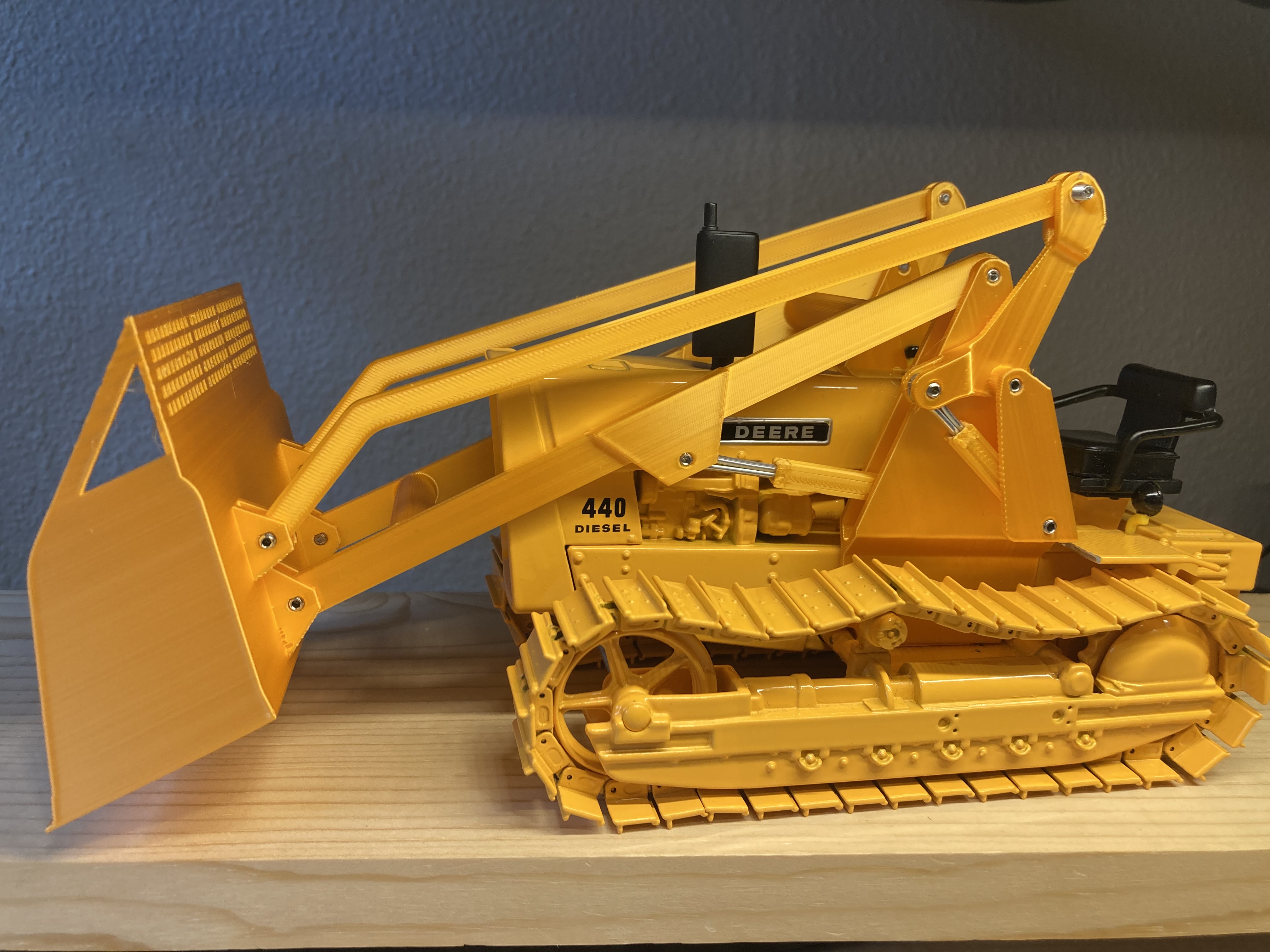
<p>ERTL makes a die cast model of this late 1950's crawler in two versions – with and without a dozer blade. They do not offer a version with the bucket loader. With a little determination and a few extra pieces of hardware, an ERTL model can be disassembled and retrofitted with the loader mechanism.</p><p><strong>MATERIALS REQUIRED</strong></p><p>ERTL 1/16 Scale John Deere 440 (with or without blade)</p><p>Atomic Filament 1.75mm PLA Silky Sunset (a surprisingly good color match to my model). <br>Note the manufacturer’s recommendation for a slightly higher temperature</p><p>3M set screws (purchased from Belmetric)</p><ul><li>2 pcs. 20mm for hydraulic cylinder bases installed to the carriage mount</li><li>2 pcs. 12mm for the tilt arm to the tilt rocker (sticks out for rear implement lift – not include)</li><li>2 pcs. 10mm for the tilt rocker arm to the carriage mount (hinge requires only 6mmbut those shafts extended out as mounts for a rear attachment)</li><li>2 pcs. 10mm for the bucket boom to the carriage mount</li><li>2 pcs. 10mm for a stop in the carriage to prevent boom from lifting too high and the cotter pins coming out of their cylinders (not in photos but you will see the holes)</li><li>2 pcs. 8mm for the short cylinder to the tilt rocker</li><li>2 pcs. 8mm for the long cylinder to the bucket arm collar</li><li>2 pcs. 8mm for the boom arm to the bucket collar</li><li>2 pcs. 6mm for the tilt arm to the bucket collar</li></ul><p>Hydraulic Pistons: Used 2 pcs. 1/8” x 2 ½” Cotter Pins. If was to do it again I would consider thinner pins (3/32”?) to allow for thicker cylinder walls (but the current STLs are sized for the 1/8”)</p><ul><li>Pins for Boom cylinders = 64mm overall (top of head to end)</li><li>Pins for Tilt cylinders = 35mm overall (top of head to end)</li></ul><p><strong>PREPARING THE ERTL MODEL </strong><i>(written out only after everything was put back together so have a healthy suspicion that something was missed)</i></p><ol><li>Optional: Remove the tracks – Pry apart one joint on each track. They should clip back together when all is done but might be looser.</li><li>Remove the 4 screws holding the ballast behind the operator seat.</li><li>Remove the 2 screws holding the hitch on the belly.</li><li>Remove the 2 screws on the belly holding the cowling and remove the cowling.</li><li>Cut the rubber air intake flush with the top surface of the cowling. It will interfere with the boom’s cross-member. You can drill a hole and reinstall further forward.</li><li>Remove the 1 screw on the belly holding the operator seat.</li><li>Lift out the frame (holding the engine and the operator seat).</li><li>If you have the model If you have the model with the dozer blade, drill out the 4 rivets holding the dozer blade assembly.</li><li>Drill out the 3 rivets holding frame together.</li><li>Pry the back apart (might be painted together) until the seat, floor and fenders slide out the back.</li><li>Remove the 1 screw holding the battery on the fender.</li><li>Cut away the forward parts of the fenders (John Deere replaced the original fenders with shorted ones when sold with the front-end loader)</li></ol><ul><li>The remaining fenders should be 29mm long.</li><li>Ideally trim to the frame so that piece still rests on the top of the frame without sticking over the side and interfering with the carriage.</li><li>Drill two holes (one for the screw, one for the pilot pin) in one fender to reinstall the battery case.</li></ul><p>The carriage mount will sit flat on the span between the tracks with the frame squeezing down from the top. If loose, shim with paper and reverse the above steps to put the die cast model back together.</p><p><i>Note: The bucket was designed to print with the base down. If printed on end the mounts may be too narrow and the boom & tilt arms may bind.</i></p><p><strong>OTHER MODIFICATIONS</strong></p><ul><li><a href="https://www.printables.com/model/174543-john-deere-440-phone-tool-attachment">Phone Holder tool attachment</a> (joke entry for a Phone Holder contest) </li><li><a href="https://www.printables.com/model/203077-john-deere-440-pocket-protector-attachment">Pocket Protector tool attachment</a> (joke entry for a Pen Holder contest) </li></ul><p><strong>BACKGROUND</strong></p><p>I had the great fortune as a kid to grow up in a family lumber business with many kinds of equipment. My favorite was an old John Deere 440 crawler loader powered by a two-cylinder gasoline engine – an antique by the time I got to play with it. Its primary functions were loading sawdust & wood shavings into trucks and clearing snow – light materials that didn’t strain the lift capacity so a screen was added to the top of the bucket to increase volume capacity.</p><p>That little loader is long gone, but a few years back I looked for a die cast model. ERTL made the 440 but as a crawler only or a crawler with blade. Mildly disappointed, I bought it and it sat displayed on a shelf.</p><p>I was recently loaned a Prusa Mini …and the idea was born! An apology to the purists as some designs were fudged to manage tolerances and I didn’t design in a stop to prevent the long pins from coming out of the cylinders if the bucket is lifted too high. Even so, I’m still pleased with the finally having the version of my childhood. This is a very niche set but cheers to anyone else who wanted the loader!</p>
With this file you will be able to print John Deere 440 Crawler Front End Loader Mechanism with your 3D printer. Click on the button and save the file on your computer to work, edit or customize your design. You can also find more 3D designs for printers on John Deere 440 Crawler Front End Loader Mechanism.