K40 3D Printed Linked Screw Adjustable Z Table for Laser Cutter
thingiverse
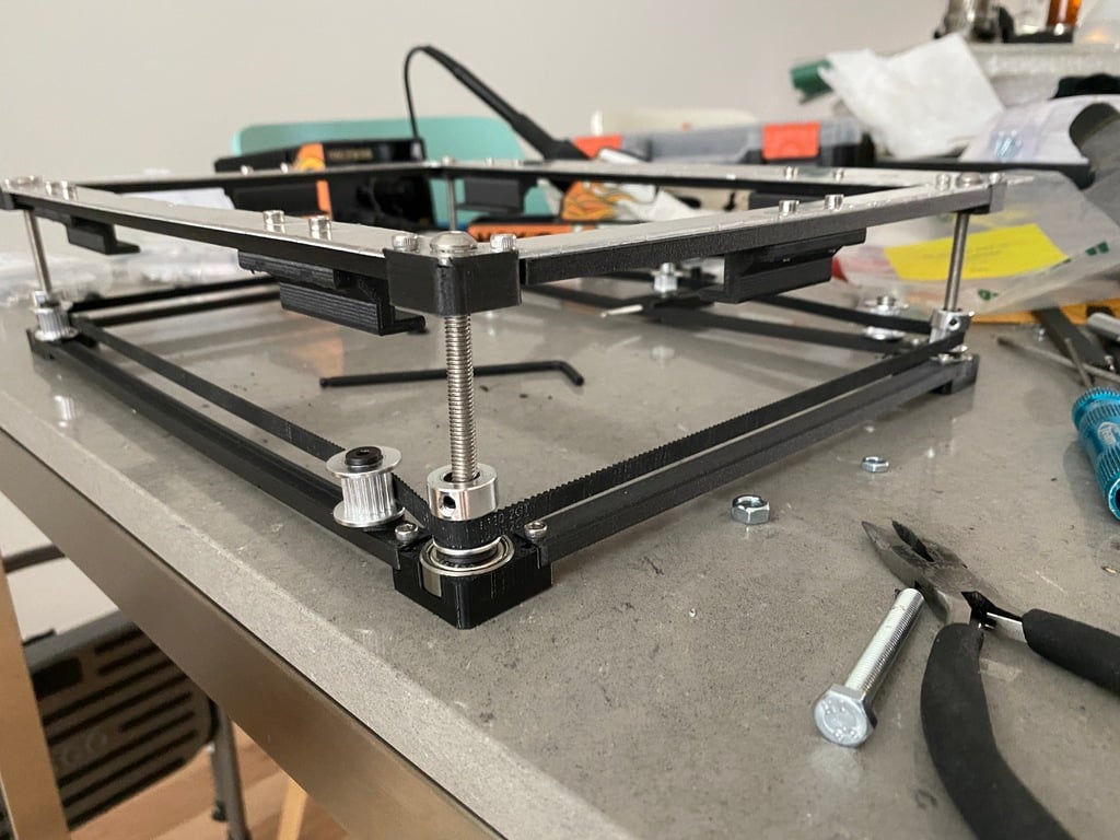
Edit: I included 4 .STEP format files which are solid models for the 300mm+ sized parts so people can edit easily to make them into multi part prints to fit their printer. I (JK3D.us ... tell all your friends!) designed and printed an almost entirely 3D printed adjustable table for the K40 laser cutter using the included metal plate with the K40. I used the original top plate for the K40 and cut it up to hold an Ebay 320x220 cutting table (Link in the BOM) , and allow me to adjust Z Height by up to 35mm with a single wrench as a jack screw table. The cutting table comes out if I want to set in a rotary holder, or swap it for something else. The top plate in my case was a rush job to cut up with a rotozip (as you can see in the pics its a rough cut but doesn't matter. You actually could just print a top plate, but I wanted protection from the laser, as most thermoplastics will be shot right through with a CO2 laser. Some of the parts need multiple of them printed and mirrors of the prints. The design prints pretty fast, the top brackets take the longest depending on what you are printing with. Total cost for the table can be cheap as I had most of the parts other than the 75mm bolts already on hand. Mirror printing - in your slicer mirror the parts that need it: Bottom Bearing Holder feet - Mirror one for the front location (Y), and then mirror both of those to the side (X) Ensure the alignment/direction arrows match the photos. Top Nut Holders - there is a Front and Rear in the files already, mirror them on the X Axis) The top brackets, and side lower brackets can be just printed multiple times and flipped to be in the right orientation. Build Notes: Unlike the CAD drawings flip the pulleys at the bottom so the belt is closer to the bearing, this will keep the forces from a tight belt on the bearing more than trying to put pressure on the top nut. The top brackets that go under the build table just slide into gaps on the top nut holders, they are secure to the table with the sets of holes in them. The Drill templates included need to be mirrored side to side, the dimensions for placement are in the pictures. The 2 outer holes are 3mm and the center hole is 8mm. The Drill templates also have edges to self align on the sides of the aluminum plate. Tap the 3mm holes on the top nut holders and the bottom bearing holders with a 3mm tap. Otherwise you may strip out the plastic easily. Secure the bearing holders in the K40 with VHB - do this (after making sure you know where you want them) without the top part attached, and without the belt on to ensure its not twisted in any way. The longer table braces that go under the cutting surface are 318mm long, this may be too big for most small format printers, you could redesign as a 2 part bracket. The nuts are a press fit into the top nut holders, use a 6mm bolt from the bottom to tighten the nut into the hex cutout in the top plastic. Bottom of the 75mm bolts is a cap to hold the bolt stable in the bearings and set an even height across the printer. Alignment Tip: Take the belt off the adjuster, then turn each screw individually to get the bed level in the cutter X and Y axis. Once that is done (remove the cutting table for access to the adjuster), but the belt back on the adjuster and tighten it and all 4 will be linked again.
With this file you will be able to print K40 3D Printed Linked Screw Adjustable Z Table for Laser Cutter with your 3D printer. Click on the button and save the file on your computer to work, edit or customize your design. You can also find more 3D designs for printers on K40 3D Printed Linked Screw Adjustable Z Table for Laser Cutter.